HVAC / Heat Pumps
Technical Data Manual for Vitocal 100-WA Heat Pump
Comprehensive technical data and installation guide for the Viessmann Vitocal 100-WA water source heat pump. Includes specifications, piping, electrical, and system requirements.
Table of contents
Manual images
Click an image to enlargeImportant Information
This manual provides technical data and installation guidelines for the Vitocal 100-WA water source heat pump. It is intended for use by licensed contractors. Key requirements include maintaining a mechanical room temperature above 60°F (15°C), ensuring proper antifreeze levels in closed-loop systems, and adhering to local electrical and plumbing codes.
Product Overview
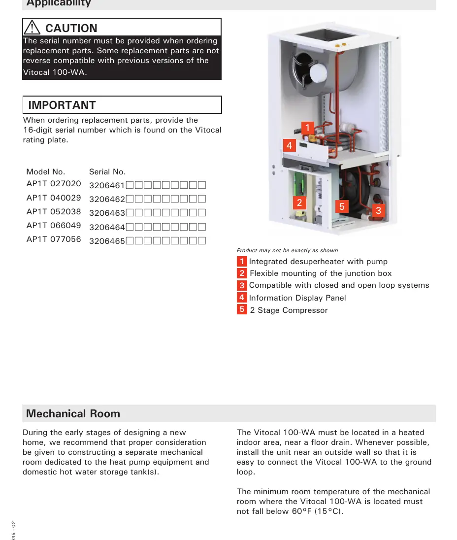
The Vitocal 100-WA is a two-stage packaged water source heat pump designed for heating and cooling buildings and producing domestic hot water (DHW). It features an integrated desuperheater and is suitable for both open and closed-loop operations.
Mechanical Room Requirements
The unit must be located in a heated indoor area, ideally near a floor drain and an outside wall for easier ground loop connection. The mechanical room temperature must not fall below 60°F (15°C).
Installation and Connections
Piping: Use a two-hand wrench method when tightening fittings to prevent pipe twisting. Support all piping using hangers; do not allow the unit to support the weight of the piping. Use isolation valves to isolate system components.

Ductwork: Design ductwork to conform to ACCA Manual D. Ensure the return air duct is not undersized to prevent poor performance and blower pulsation. Static pressure for residential design should not exceed 0.3 inches.
Electrical: Electrical installations must comply with the National Electrical Code (NEC) or Canadian Electrical Code (CEC). Ensure the control is grounded and that L1, L2, and G are not interchanged.
System Types
Closed Loop: Requires a minimum flow rate of 3 GPM/ton. You must maintain a minimum of 25% propylene glycol antifreeze solution at all times to prevent system freezing and damage.
Open Loop: Requires a well of sufficient capacity and good water quality. A 18-20 mesh strainer is recommended to keep debris out of the heat exchanger. Never pump pond or lake water directly through the unit.
Domestic Hot Water (DHW)
The unit includes an integrated desuperheater. When connecting to a DHW tank, use isolation valves and two boiler drain valves for purging. A horizontal swing check valve is required to prevent tank overheating.

Maintenance
Regularly check and change air filters, as most require monthly attention. Do not run the system during construction or remodeling, as dust can clog the air coil and condensate drain, voiding the warranty.
Manufacturer information
Viessmann Climate Solutions
Practical help
Common problems
System freezing in closed loop
Ensure a minimum of 25% propylene glycol antifreeze solution is maintained in the unit and ground loop at all times.
Poor system performance or blower pulsation
Check for undersized return air ducts or inadequate insulation in attic installations.
Noise and vibration transmission
Use flexible couplings for ductwork and shock-absorbing pads to isolate the unit from hard surfaces like concrete floors.
Clogged air coil or condensate drain
Do not operate the system during construction or remodeling; dust accumulation will void the warranty.
Before use
- Verify the model and serial number on the rating plate.
- Ensure the mechanical room temperature is at least 60°F (15°C).
- Confirm electrical supply matches the unit requirements (208/230V).
- Check that all piping connections are supported by hangers, not the unit.
- Ensure proper antifreeze levels for closed loop systems.
- Install a high-efficiency air filter.
Specs in practice
- Heating/Cooling Capacity
- The output range in MBH and kW, determining the unit's ability to heat or cool the space.
- MCA (Minimum Circuit Ampacity)
- The minimum electrical current capacity required for the circuit supplying the unit.
- Static Pressure
- The resistance in the ductwork; should not exceed 0.3" for residential design.
- EER (Energy Efficiency Ratio)
- Indicates the cooling efficiency of the heat pump.
Images and diagrams
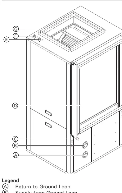
- Piping Connections: Illustrates the return/supply for ground loop, condensate line, and DHW connections.
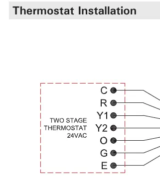
- Wiring Diagrams: Detailed schematics for power supply and thermostat connections for various models.
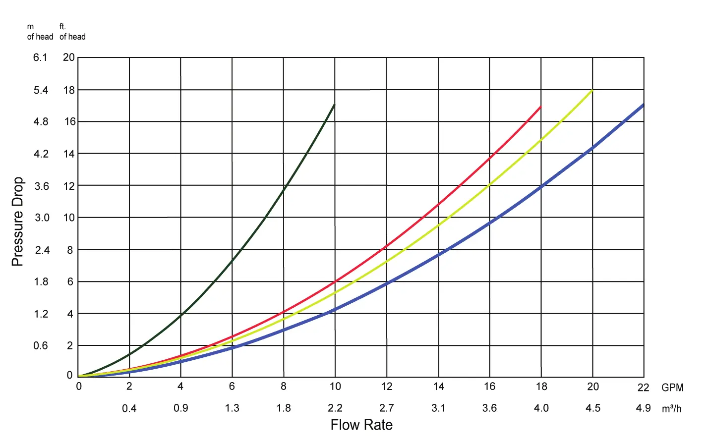
- Pressure Drop Chart: Shows the relationship between flow rate and pressure drop for different models.
Model compatibility
- Requires a 2-stage heating/cooling, 7-day programmable thermostat.
- Not compatible with pond or lake water directly in open loop systems.
- Do not use PVC or CPVC plastic piping on ground loop connections.

Manual page author
Emily Carter
User documentation editor
Prepares concise manual descriptions and highlights the most useful setup, operation, and maintenance information for readers.