HVAC / Water Heaters
Technical Data Manual for Viessmann Vitocell 100-B Water Heater
Quick guide for the Viessmann Vitocell 100-B series dual-coil indirect-fired domestic hot water storage tank. Includes technical specifications, installation guidelines, connection diagrams, and safety warnings.
Table of contents
Manual images
Click an image to enlargeImportant Information from the Manual
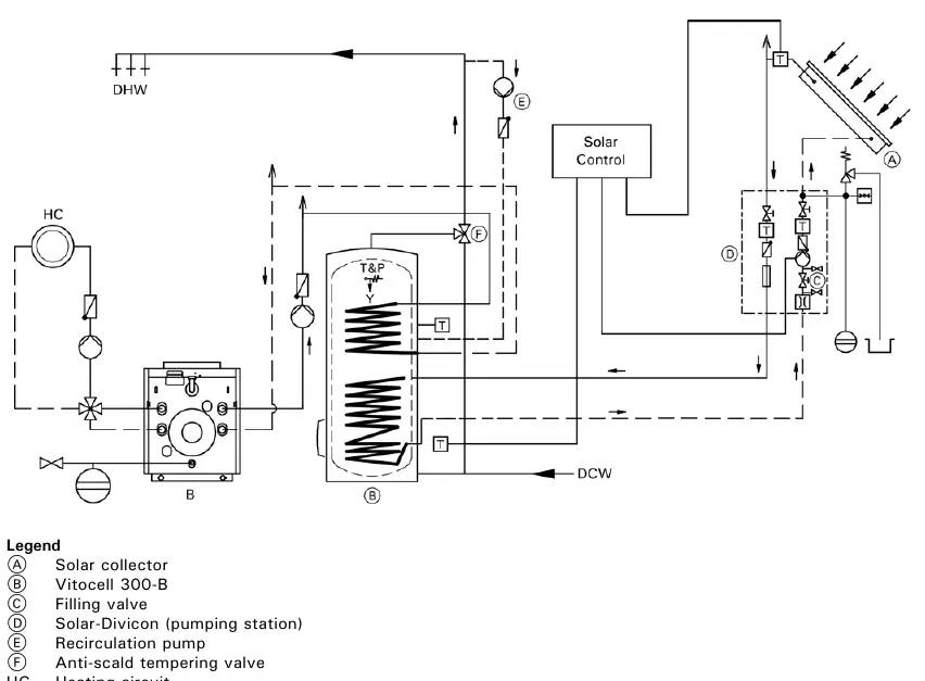
The Viessmann Vitocell 100-B is a dual-coil, indirect-fired domestic hot water storage tank. Important: This tank version is not suitable for steam heating applications. Due to high temperatures generated by solar heating systems, a thermostatic mixing valve must be installed to limit domestic hot water temperature to a maximum of 140°F (60°C) to prevent scalding.
Product Overview
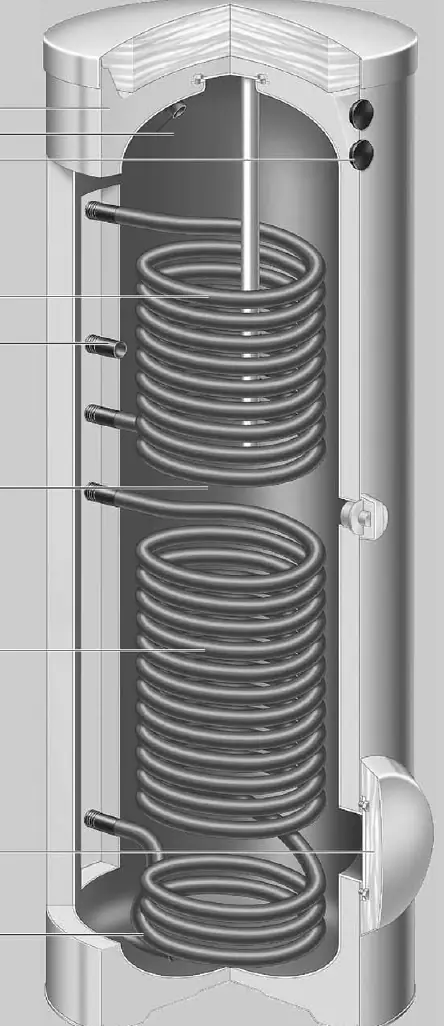
The Vitocell 100-B features a corrosion-resistant steel tank with Ceraprotect enamel coating and a magnesium anode for cathode protection. It is designed for dual-mode heating using solar collectors (via the lower coil) and a hot water heating boiler (via the upper coil). The 79 USG (300 L) model uses hard PUR foam insulation, while the 119 USG (450 L) model uses removable soft PET insulation.
Technical Specifications
The tank is available in two capacities: 79 USG (300 L) and 119 USG (450 L). Key technical data includes:
- Maximum Working Pressure: 150 psig on both heat exchanger and DHW sides.
- Connections: 1-inch NPT threads for coils and domestic water connections.
- Recovery Rates: Vary based on supply water temperature and boiler output. Refer to the technical data tables for specific MBH and GPH ratings.
- Standby Losses: 5.6 MBH/24h for the 79 USG model and 6.6 MBH/24h for the 119 USG model.
Standard Equipment
The tank is supplied with the following components packed separately:
- Temperature and pressure relief valve.
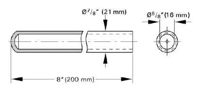
- Brass elbow with sensor well.
- Brass tee (1 inch).
- Brass hex bushing (1 inch x 3/4 inch).
- Brass cap (1 inch).
- Plug (R1 inch).
- Two thermometers (°F/°C).
Installation and Connections
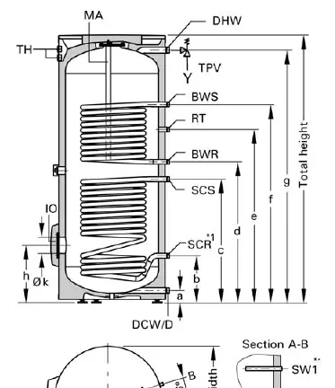
The tank includes welded sensor wells for the DHW tank temperature sensor (aquastat) and thermometer. Adjustable leveling bolts are provided for installation. For solar heating systems, Viessmann recommends placing the DHW tank temperature sensor in the solar collector return (SCR) using the provided brass elbow with sensor well. The boiler control sensor should be placed in the SW1 sensor well.
System Design Guidelines
When installing, ensure the water quality is potable. If backflow preventers are required, a domestic water expansion tank is recommended in the cold water inlet piping. The temperature and pressure relief valve must be installed according to local code requirements. If the heating water supply temperature exceeds 230°F (110°C), an additional safety high limit must be installed to prevent the tank temperature from rising above 203°F (95°C).
Warranty and Maintenance
Viessmann reserves the right to withdraw the warranty if the product is improperly installed, misapplied, or if non-approved components are used. The tank must be used with potable water; using it to heat other media voids the warranty. Chloride and sulfate concentrations in the water must be within acceptable limits.
Manufacturer information
Viessmann Climate Solutions
Practical help
Common problems
Water temperature too high
Install a thermostatic mixing valve to limit DHW temperature to 140°F (60°C).
Steam heating application
This tank is not suitable for steam heating applications.
Warranty void
Ensure water is potable quality and do not use non-approved components.
Before use
- Verify water quality is potable.
- Ensure installation meets local plumbing codes.
- Install a thermostatic mixing valve for solar applications.
- Check that the boiler output meets the required recovery rate.
- Install the provided temperature and pressure relief valve.
Specs in practice
- Recovery rate
- The amount of hot water the tank can produce based on boiler output and supply temperature.
- Standby losses
- Energy lost while the tank is holding hot water.
- Working pressure
- Maximum pressure the tank can handle (150 psig).
Images and diagrams
- Cross Section: Shows internal coils, insulation, and sensor locations.
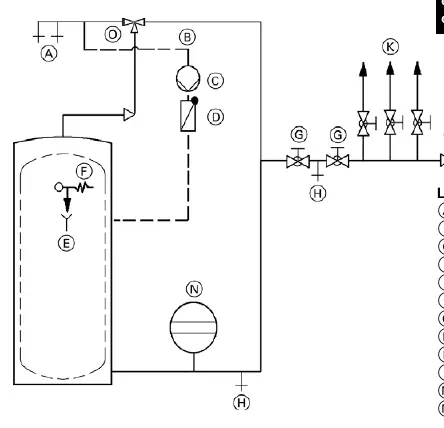
- Installation Example: Illustrates connections between solar collector, boiler, and tank.
- Sensor Well: Details the welded sensor well dimensions.
Model compatibility
- Compatible with solar collectors and hot water heating boilers.
- Not suitable for steam heating.

Manual page author
David Miller
Documentation analyst
Organizes user manual content into clear summaries, with attention to model details, product context, and everyday usability.