HVAC / Water Heaters
Installation and Maintenance Manual for Tesy AquaThermica Compact HPWH 3.2 100L/150L
A comprehensive installation and maintenance guide for the Tesy AquaThermica Compact heat pump water heater. Includes detailed diagrams for wall mounting, hydraulic connections, air ducting configurations, and electrical wiring.
Table of contents
Manual images
Click an image to enlargeQuick Guide from the Manual
This document serves as the visual appendix for the installation and maintenance of the Tesy AquaThermica Compact heat pump water heater (models 100L and 150L). It provides essential diagrams for safe handling, wall mounting, air ducting, hydraulic connections, and electrical wiring. Always ensure the unit is transported and installed in an upright position as indicated in the diagrams.
Handling and Unpacking
The unit must be transported in an upright position. Use a trolley for transport. When unpacking, ensure the unit is handled carefully. Do not lay the unit on its side or upside down, as this may damage the internal components.
Installation
The unit is designed for wall mounting. Ensure the wall is capable of supporting the weight of the filled water heater. Follow the specific drilling and mounting patterns provided in the diagrams (fig. 12, 16a, 16d). Maintain the required clearances from walls and ceilings to ensure proper airflow and service access.
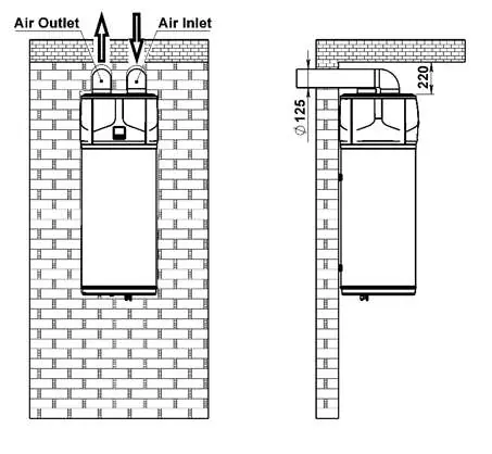
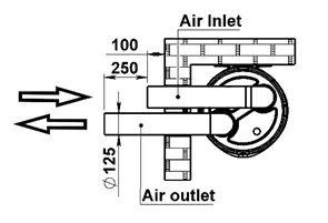
Air Ducting Configurations
The AquaThermica Compact allows for various air ducting configurations to suit the installation environment. Ensure that air inlet and outlet ducts are installed according to the diagrams (fig. 13, 14, 15, 17a, 18, 19). Proper ducting is critical for the efficient operation of the heat pump.
Hydraulic Connections
Connect the cold water (CW) and hot water (HW) lines according to the provided hydraulic diagrams (fig. 20). Ensure all connections are sealed properly. The system includes provisions for safety valves and drainage.
Electrical Connections
The electrical wiring diagram (fig. 23) details the connections for the compressor, fan, electric heater, and control panel. Ensure the power supply matches the specifications (220-240V; ~50Hz). All electrical work must be performed by a qualified technician.
Solar and PV Integration
The unit supports integration with external systems, such as solar or PV panels, as shown in the connection diagrams (fig. 27). This allows for optimized energy usage.
Manufacturer information
TESY
Practical help
Common problems
Incorrect transport position
Always transport the unit in an upright position as shown in fig. 1. Do not lay it on its side.
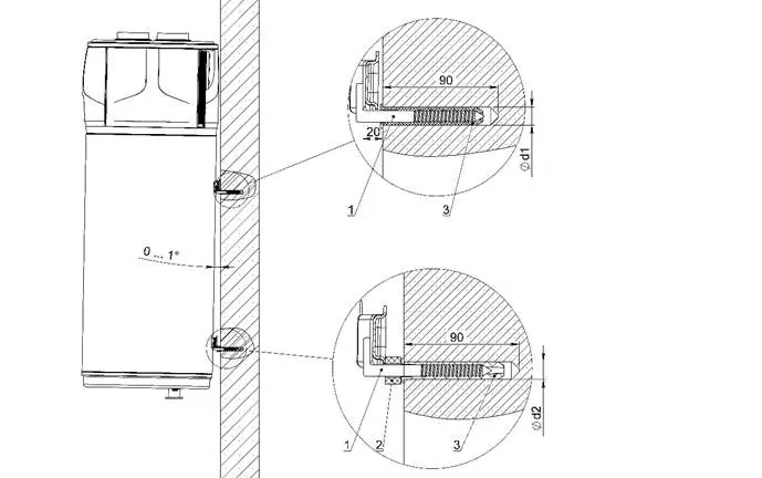
Improper wall mounting
Use the drilling templates and mounting hardware specified in fig. 12 and 16a to ensure secure attachment to the wall.
Airflow restriction
Ensure air inlet and outlet ducts are installed without obstructions and follow the configurations in fig. 13-19.
Before use
- Verify the wall can support the weight of the filled water heater.
- Ensure the unit is transported and positioned upright.
- Check that all hydraulic connections (CW/HW) are secure and leak-free.
- Confirm that air ducts are installed according to the required configuration.
- Verify electrical connections match the 220-240V power supply.
- Ensure the safety valve is correctly installed.
Specs in practice
- CW / HW Connections
- G1/2B standard hydraulic connections for cold and hot water.
- Air Duct Diameter
- 125 mm diameter for air inlet and outlet ducts.
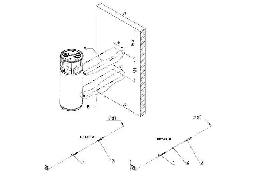
- Wall Mounting
- Requires specific drilling patterns (M1, M2) and secure anchor bolts.
Images and diagrams
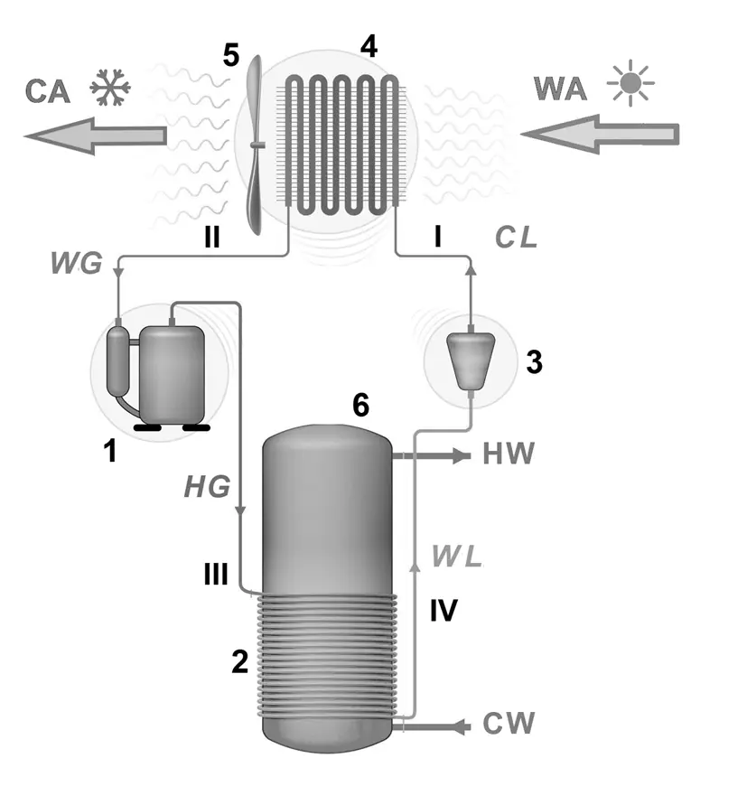
- Fig. 0: General system overview showing the heat pump cycle.
- Fig. 16a/16d: Detailed wall mounting instructions and dimensions.
- Fig. 20: Hydraulic connection schematic.
- Fig. 23: Comprehensive electrical wiring diagram.
Model compatibility
- Compatible with solar/PV integration (fig. 27).
- Designed for indoor installation with specific air ducting requirements.

Manual page author
Emily Carter
User documentation editor
Prepares concise manual descriptions and highlights the most useful setup, operation, and maintenance information for readers.