HVAC / Water Heaters
Ariston Lydos ECO ABS PW 100V Electric Water Heater User Manual
Quick guide for the Ariston Lydos ECO ABS PW 100V electric water heater. Includes installation, operation, maintenance, and troubleshooting instructions.
Table of contents
Manual images
Click an image to enlargeQuick guide from the manual
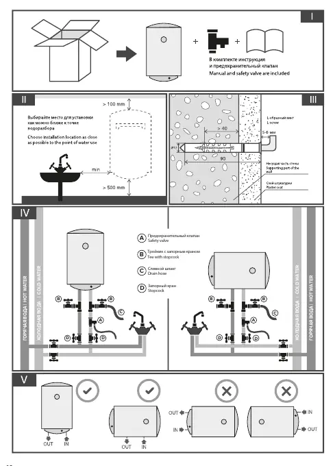
This manual provides essential information for the installation, operation, and maintenance of the Ariston Lydos ECO ABS PW series electric water heaters. Before using the appliance, ensure the tank is filled with water by opening the hot water tap on the mixer and then the cold water supply tap. Only connect the appliance to the power source after it is completely filled with water.
Installation
Installation must be performed by a qualified technician. The water heater should be mounted on a solid wall using brackets and hooks (diameter at least 12 mm). Ensure the mounting can support three times the weight of the filled heater. Maintain at least 50 cm of free space under the appliance and 10 cm from the ceiling for maintenance. Install the safety valve on the cold water inlet (marked with a blue ring) and use a T-piece with a shut-off valve for easier maintenance and draining.
Operation
Use the ON/OFF button to switch the appliance on. Set the desired temperature (40°C to 80°C) using the '+' and '-' buttons. The appliance features several modes:
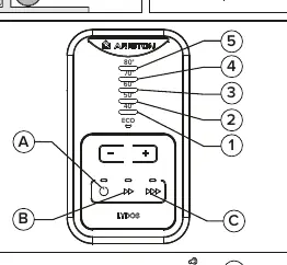
- Standard mode: Minimum power (60%).
- FAST mode: Average power (80%).
- BOOST mode: Maximum power (100%).
- ECO EVO function: A self-learning software that optimizes heating based on your hot water consumption habits.
- Anti-legionella cycle: Automatically heats water to 60°C for 1 hour to prevent bacteria growth.
- Anti-freeze function: Automatically activates if the water temperature drops below 5°C.
Maintenance
Regular maintenance is required to ensure longevity:

- Magnesium Anode: Must be checked annually and replaced if worn (residual volume less than 30%). This is a consumable item and not covered by warranty.
- Safety Valve: Regularly check that it is not blocked or damaged. It is normal for water to drip from the drain hole during heating due to thermal expansion.
- Draining: If there is a risk of freezing, drain the water heater by disconnecting the power, closing the cold water supply, opening the hot water tap, and using the drain valve on the T-connector.
Troubleshooting
If a malfunction occurs, all LEDs on the control panel will flash. To diagnose, press and hold the ON/OFF and FAST buttons for 5 seconds. Error codes are indicated by the LEDs:
- LED 60°C: NTC sensor fault.
- LED 70°C: Heating element fault.
- LED 80°C: Water overheating.
- LEDs 50°C & 80°C: Data flash error.
- LEDs 60°C & 80°C: NFC communication error.
- LEDs 70°C & 80°C: General overheating.
- LEDs 50°C, 60°C & 70°C: NFC error.
- LEDs 60°C, 70°C & 80°C: No water.
Safety
Do not open the water heater body. Do not use the appliance with a damaged power cable. Do not climb onto the appliance or leave objects on top of it. Ensure the appliance is properly earthed. Do not use insecticides, solvents, or aggressive detergents for cleaning.
Manufacturer information
Ariston
Practical help
Common problems
All LEDs on the control panel are flashing
The appliance has detected a malfunction. Perform the diagnostic procedure (hold ON/OFF and FAST buttons for 5 seconds) to identify the error code.
Water dripping from the safety valve
This is a normal process caused by thermal expansion of water during heating. It is recommended to connect the drain hole to a sewer system.
No hot water
Check if the appliance is switched on, the power supply is active, and the thermostat or heating element is not broken.
Before use
- Ensure the tank is filled with water before connecting to power.
- Check the flange for leaks.
- Ensure the appliance is properly earthed.
- Install the safety valve on the cold water inlet.
- Ensure the water hardness is at least 12°F.
Specs in practice
- Magnesium Anode
- Protects the inner tank from corrosion. Must be checked annually and replaced if worn.
- Safety Valve
- Prevents water from returning to the supply line and protects the tank from excessive pressure.
Images and diagrams
- Fig 1: Installation clearance requirements.
- Fig 2: Hydraulic connection diagram showing safety valve and T-piece.
- Fig 3: Control panel layout and LED indicators.
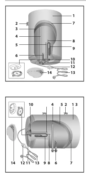
- Fig 4: Internal components including flange, heating element, and anode.
Model compatibility
- The device is not designed for water with hardness less than 12°F.
- If water hardness is above 25°F, a softener must be used to prevent scale buildup.

Manual page author
Emily Carter
User documentation editor
Prepares concise manual descriptions and highlights the most useful setup, operation, and maintenance information for readers.