Home / Electrical Timers
Installation Instructions for Vulcan Steamer Replacement Timer Kit 00-913102-0176A
A comprehensive installation guide for the Vulcan Steamer Replacement Timer Kit (00-913102-0176A). This manual provides step-by-step instructions for replacing the timer, including wiring diagrams for various steamer models, safety...
Table of contents
Quick guide from the manual
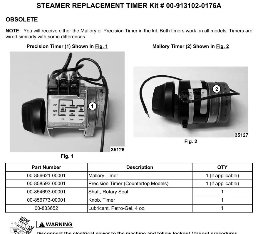
This document provides instructions for installing the Vulcan Steamer Replacement Timer Kit (00-913102-0176A). The kit may contain either a Mallory or a Precision timer; both are compatible with all models, though wiring may differ slightly. Important: Always disconnect electrical power and follow lockout/tagout procedures before beginning any work.
Installation Procedure
- Remove the right side panel: Remove the screws from the bottom of the panel, pull the bottom out, and slide the panel down to clear the top cover.
- Disconnect old timer: Note the existing wiring configuration and disconnect the old timer.
- Handle new timer with care: Do not touch the cams or switch levers with hands or tools. Do not remove any jumper wires on the Precision brand timer.
- Connect new timer wiring: Follow the specific wiring instructions for your steamer model (see Wiring Instructions section).
- Verify orientation: Ensure the orientation nub on the front face of the timer engages the small hole on the back side of the steamer front panel.
- Secure the shaft: Use the new seal nut provided in the kit to secure the shaft to the steamer panel. Torque the seal nut up to, but not over, 15 in. lbs.
- Final assembly: Install the right side panel.
- Test operation: Restore power, turn the steamer on, and set the timer to 5 minutes. Verify that the alarm sounds and the cook light goes out simultaneously near 0 minutes.
Wiring Instructions
Wiring connections depend on the specific steamer model. Ensure you identify your model correctly before connecting wires.
Models C24EA6/10 or C24GA6/10
- Wire #6 (RED) on Upper (1, Timer terminal 11)
- Wire #9 (BLUE) on Lower (1, Timer terminal 11)
- Wire #27 (WH) on Upper (2, Timer motor)
- Wire #30 (WH) on Lower (2, Timer motor)
- Wire #12 (BRN) on Upper (3, Timer terminal 14)
- Wire #14 (BRN) on Lower (3, Timer terminal 14)
- Wire #15 (ORG) on Upper (4, Timer terminal 23)
- Wire #20 (YEL) on Lower (4, Timer terminal 23)
- Note: The wire on timer terminal #21 must be taped off and insulated. It is not used on the Precision Timer with exposed micro switches.
Models C24EA3/5, HC24EA3/5, C24EO3/5, HC24EO3/5
- Wire #14 (RED) (1, Timer terminal 11). Pro Model Only: Insulate one #14 terminal connection; the Pro model requires only one terminal connection for #14.
- Wire #18 (2, Timer Motor)
- Wire #20 (3, Timer terminal 14)
- Wire #19 (4, Timer terminal 23)
- Note: The wire on terminal #21 must be taped off and insulated.
Safety and Handling
Always adhere to lockout/tagout procedures. When installing the timer, avoid touching internal components like cams or switch levers. Ensure all unused wires, specifically those on terminal #21, are properly taped off and insulated to prevent short circuits.
Practical help
Common problems
Timer not functioning after installation
Verify that all wires are connected to the correct terminals according to your specific model diagram. Ensure the wire on terminal #21 is insulated if not used.
Seal nut is loose or overtightened
Secure the shaft using the new seal nut provided. Torque to a maximum of 15 in. lbs.
Pro model wiring confusion
For Pro models, only one #14 terminal connection is required. Insulate the other #14 connection.
Before use
- Disconnect electrical power to the machine.
- Follow lockout/tagout procedures.
- Identify if you have a Mallory or Precision timer.
- Verify your specific steamer model number to select the correct wiring diagram.
- Ensure you have the new seal nut from the kit.
Specs in practice
- Seal Nut Torque
- Maximum 15 in. lbs. Do not overtighten.
Images and diagrams
- Fig 1 & 2: Identification of Mallory vs. Precision timers.
- Fig 3: Panel removal instructions.
- Fig 4 & 5: Wiring terminal identification for specific models.
Model compatibility
- Compatible with models: C24EA6/10, C24GA6/10, C24EA3/5, HC24EA3/5, C24EO3/5, HC24EO3/5, C24GA, C24DA.
- Both Mallory and Precision timers work on all listed models.

Manual page author
Emily Carter
User documentation editor
Prepares concise manual descriptions and highlights the most useful setup, operation, and maintenance information for readers.