Accessories / Mounts & Stands
WALI 1330LM-ES Wall Mount Installation Manual
Quick installation guide for the WALI 1330LM-ES wall mount. Includes a complete parts list, step-by-step mounting instructions for brick and wood walls, and essential safety precautions.
Table of contents
Manual images
Click an image to enlargeQuick guide from the manual
This document provides installation instructions for the WALI 1330LM-ES wall mount. Before beginning, ensure you have all the necessary tools and verify your wall type. The mounting hardware included is specifically designed for brick and wood surfaces; it is not suitable for steel studs or cinder block walls. If you are unsure about your wall type or the installation process, consult a qualified installation contractor.
Supplied Parts List
Before starting, verify that you have all the following components:
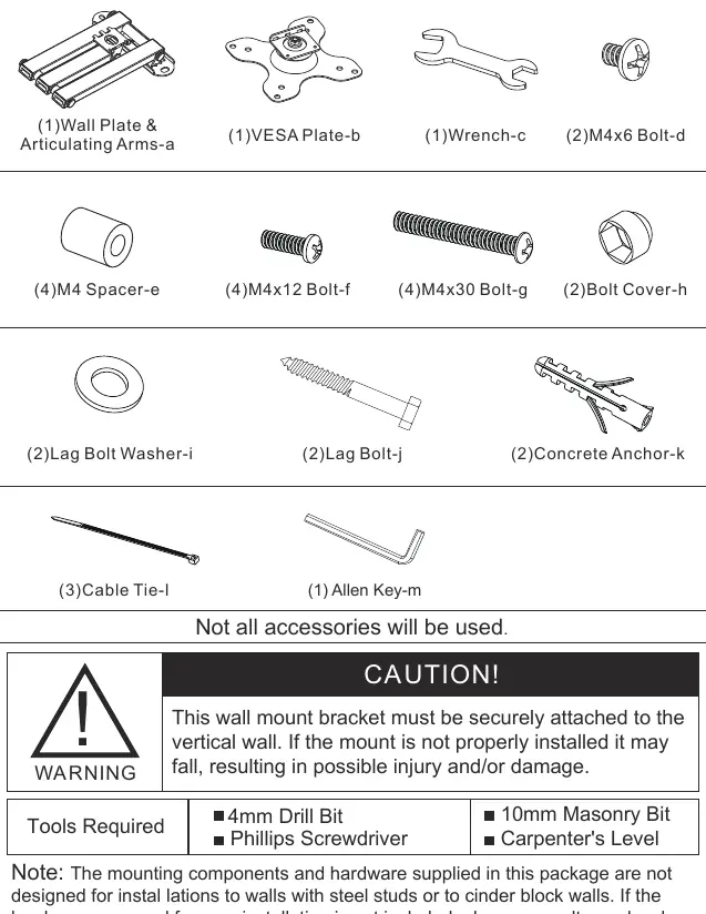
- Wall Plate & Articulating Arms (a)
- VESA Plate (b)
- Wrench (c)
- M4x6 Bolt (d)
- M4 Spacer (e)
- M4x12 Bolt (f)
- M4x30 Bolt (g)
- Bolt Cover (h)
- Lag Bolt Washer (i)
- Lag Bolt (j)
- Concrete Anchor (k)
- Cable Tie (l)
- Allen Key (m)
Installation
Step 1: Install the Wall Plate to the Wall
Brick Mount: Drill holes using a 10mm masonry bit to a depth of 65mm. Insert concrete anchors (k) and secure the wall plate using lag bolts (j) and washers (i).
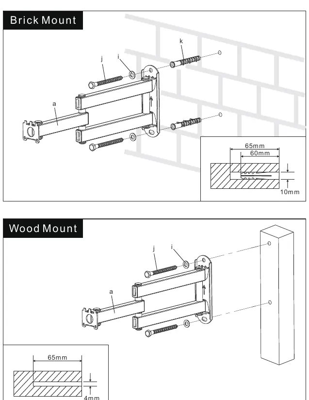
Wood Mount: Drill holes using a 4mm drill bit to a depth of 65mm. Secure the wall plate directly to the wood stud using lag bolts (j) and washers (i).
Step 2: Attach VESA Plate to the Mounting Hole
Attach the VESA plate (b) to the back of your device using the appropriate M4 bolts (f or g) and spacers (e) if necessary. Ensure the plate is oriented correctly as indicated by the arrow.
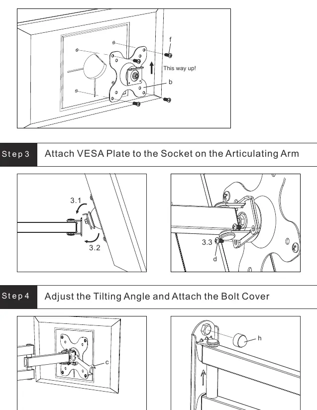
Step 3: Attach VESA Plate to the Socket on the Articulating Arm
Connect the VESA plate (b) to the socket on the articulating arm (a). Secure the connection using the M4x6 bolts (d).
Step 4: Adjust the Tilting Angle and Attach the Bolt Cover
Adjust the tilting angle to your preference. Once positioned, attach the bolt cover (h) to hide the mounting hardware.
Safety Information
- Carefully open the carton and lay out contents on a protective surface to avoid damage.
- Do not use damaged or defective parts.
- Use proper safety equipment during installation.
- Do not use this product for any purpose or in any configuration not explicitly specified in this instruction.
Practical help
Common problems
Mounting on steel studs or cinder block walls
The included hardware is not designed for these wall types. Consult your local hardware store for appropriate mounting hardware.
Uncertain about wall type or installation safety
Consult a qualified installation contractor for assistance.
Before use
- Check package contents against the Supplied Parts List.
- Ensure you have a 4mm drill bit, Phillips screwdriver, 10mm masonry bit, and a carpenter's level.
- Verify the wall type (Brick or Wood).
- Read all instructions before attempting installation.
Images and diagrams
- Step 1 illustrates the specific drilling requirements for brick versus wood surfaces.
- Step 3 shows the locking mechanism for attaching the VESA plate to the arm.
Model compatibility
- Designed for Echo Show 15.
- Not compatible with steel studs or cinder block walls.

Manual page author
Michael Turner
Technical manual editor
Reviews PDF manuals for structure, safety notes, and practical product details so readers can find the right information quickly.