Lighting / Outdoor Landscape
User Manual for WeteLux 10W LED Floodlight with Motion Sensor
Quick guide for the WeteLux 10W LED Floodlight with 150° PIR motion sensor. Includes installation instructions, wiring diagrams, sensor adjustments, and technical specifications.
Table of contents
Manual images
Click an image to enlargeQuick Guide
This document provides essential instructions for the WeteLux 10W LED Floodlight (Article No. 90 08 26). The device is designed for indoor and outdoor use and features a 150° PIR motion sensor. Installation must be performed by a qualified electrician. Ensure the power is disconnected at the circuit breaker before beginning any installation work.
Product Overview
The floodlight consists of the following main components:
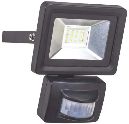
- Motion Sensor: Detects movement within the field of view.
- Safety Glass: Protects the LED panel.
- Wall Mount: Used for securing the unit to a wall or ceiling.
- Adjusting Knobs: Located on the sensor, these control SENS (sensitivity), TIME (duration), and LUX (light threshold).
- Cable Gland: Used for secure power cable entry.
Safety Instructions
To prevent malfunctions, damage, or injury, observe the following:
- The device must be connected to a 230V~ / 50Hz AC power supply.
- A protective earth (PE) cable must be connected. If no earth cable is available, do not install the unit.
- Do not operate the floodlight in or under water.
- Maintain a minimum distance of 1 meter between the floodlight front and other objects.
- Do not cover the unit during operation.
- The device is not suitable for use in altitudes over 2000 meters.
- If the housing is damaged, stop using the device immediately.
Installation
Installation must be carried out by a qualified technician familiar with local electrical regulations.


- Ensure the power supply is completely disconnected and secured against unauthorized restart.
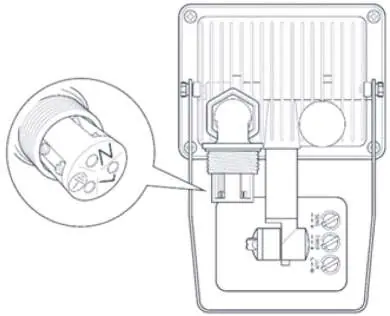
- Unscrew the lock nut from the cable gland and guide the power cable through the waterproof grommet.
- Connect the three wires to the terminals: N (Blue), L (Brown/Black), and PE (Green/Yellow).
- Secure the wall mount to a stable surface using suitable screws and dowels.
- Tilt the floodlight to the desired angle and tighten the hinge adjusting screws.
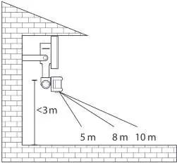
- Verify the motion sensor's field of view before final mounting.
Operation and Adjustments
The motion sensor can be adjusted horizontally and vertically. Use the three knobs on the sensor to customize performance:
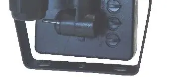
- SENS: Adjusts the motion detection sensitivity.
- TIME: Sets the illumination duration after motion stops (adjustable from 10±5 seconds to 10±1 minutes).
- LUX: Sets the light threshold. Turn towards the sun symbol for operation in brighter conditions, or towards the moon symbol for operation only in darkness.
Cleaning and Maintenance
Clean the housing only with a dry or lightly moistened cloth. Do not use aggressive chemicals or abrasives. Keep the motion sensor lens clean at all times to ensure proper detection.
Technical Data
The floodlight operates at 230V~ 50Hz with a power consumption of 10W. It provides 800 lm output at 6500 K. The detection angle is 150° with a range of 8 to 10 meters. The unit is IP44 rated and weighs 382g.
Practical help
Common problems
Light glows faintly when switched OFF
Switch the L and N cables in the terminals.
Motion sensor triggers randomly
Check for strong transmitters (amateur radio, mobile masts) nearby, which can cause interference.
Sensor range is inconsistent
The range depends on ambient temperature; it is higher in cold environments.
Before use
- Ensure mains voltage matches the type label (230V~ / 50Hz).
- Verify that a protective earth (PE) cable is available.
- Ensure the installation site is stable and free from vibrations.
- Check for nearby flammable materials or liquids.
- Ensure the power is disconnected at the circuit breaker before starting.
Images and diagrams
- Wiring diagram shows connection for N (Blue), L (Brown/Black), and PE (Green/Yellow).
- Sensor adjustment knobs are located on the bottom of the motion sensor.
Model compatibility
- Not dimmable.
- Not for use in altitudes over 2000m.
- Must be installed by a qualified electrician.

Manual page author
David Miller
Documentation analyst
Organizes user manual content into clear summaries, with attention to model details, product context, and everyday usability.