Power / Uninterruptible Power Supplies
User Manual for Xmart External Battery Charger
Quick guide for the Xmart External Battery Charger. Includes installation steps, wiring diagrams, operation procedures, and technical specifications for 12A and 24A models.
Quick answers from the manual
Quick answer
- The Xmart External Battery Charger is a high-capacity device requiring professional installation. It must be installed in a well-ventilated area, not in closed cabinets. Operation requires a specific sequence: connect battery breakers, turn on the UPS, then turn on the charger breaker. p. 2, 3
Key actions
- Installation Ventilation p. 2
- Startup Sequence p. 3
First start
- Follow the breaker activation sequence: Battery Banks -> UPS -> External Charger. p. 3
Show 2 more answers Show less
Technical specifications
| Parameter | Value | Meaning | Pages |
|---|---|---|---|
| 12A Model Capacity | 2600W | Power capacity for the 12A model | p. 4 |
| 24A Model Capacity | 5200W | Power capacity for the 24A model | p. 4 |
| AC Input Range | 110Vac-300Vac | Acceptable AC input voltage range | p. 4 |
| DC Output Voltage | 273Vdc +/- 1% | Charging voltage output | p. 4 |
Where to find it in the PDF
- Safety Instructions p. 2
- Installation p. 2, 3
- Operation p. 3
- Technical Specifications p. 4
Table of contents
Manual images
Click an image to enlargeQuick Guide
The Xmart External Battery Charger is a high-capacity device designed to charge battery banks. It requires professional installation and must be operated by qualified personnel. The unit must be installed in a well-ventilated area to prevent overheating and permanent damage.
Description
This product is a high-capacity 240V DC battery charger. It is powered by a 220V AC main line (supporting a range of 110Vac to 300Vac) and generates a 273Vdc charging voltage. Two models are available: 12A and 24A.
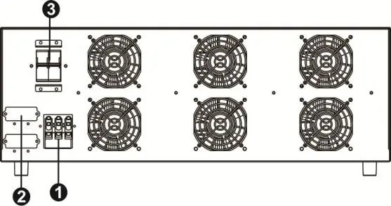
Installation
Important: This unit must not be installed in closed boxes or cabinets. It requires fresh air to flow through the ventilation system to cool the power circuits. Installing it in an enclosed space will cause the internal temperature to exceed the maximum operating limit, leading to permanent damage.
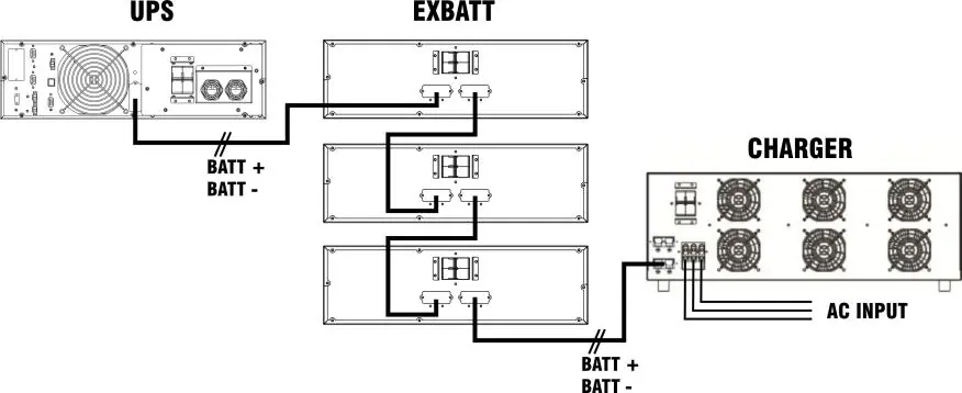
Wiring and Connection:
- Ensure the battery bank and UPS operating DC voltage are compatible with the charger.
- Connect the unit to the battery banks and UPS according to the provided wiring diagram.
- The charger must be connected to an appropriate electrical service as specified on the unit's label.
Operation
Once the charger is installed, follow this sequence to start the system:
- Set the breakers that connect the battery banks to each other (and to the UPS) to the ON position.
- Turn on the UPS according to its specific procedure.
- Set the External Charger breaker to the ON position.
Once these steps are completed, the UPS internal batteries and external battery banks are connected in parallel with the charger's DC output, and the batteries will begin recharging.
Technical Specifications
The charger is available in two configurations:
- 12A Model: 2600W capacity, 30A max input current.
- 24A Model: 5200W capacity, 60A max input current.
- Input Voltage: 208/220/230/240Vac (Range: 110Vac-300Vac).
- Output Voltage: 273Vdc +/- 1%.
- Operating Conditions: 0-40°C, humidity < 95% (non-condensing).
Support & Warranty
If a failure or problem is detected, contact an authorized service center or dealer. The warranty covers defects in materials and workmanship. It does not cover batteries, additional equipment, or failures caused by improper installation, unauthorized modifications, or misuse. In Europe, the warranty is 2 years on electronic parts and internal batteries.
Practical help
Common problems
Unit overheating or permanent damage
Ensure the unit is not installed in a closed box or cabinet. It requires fresh air circulation for cooling.
Charger not functioning
Verify that the AC Input Breaker is in the ON position and that the input power supply is within the 110Vac-300Vac range.
Before use
- Verify that the installation location allows for proper ventilation.
- Ensure the battery bank and UPS DC voltage are compatible with the charger.
- Confirm the AC power supply matches the technical specifications.
- Check that all connections to the battery bank and UPS are secure.
Show more Show less
Specs in practice
- Operating Temperature
- The ambient temperature range for safe operation is 0°C to 40°C.
Images and diagrams
- The wiring diagram illustrates the parallel connection between the UPS, the External Battery Bank (EXBATT), and the Charger.
- The rear panel diagram identifies the AC Input, the DC Connector for Batteries, and the AC Input Breaker.
Model compatibility
- Battery Bank and UPS operating DC Voltage (VDC) must be compatible with the DC Voltage generated by this unit.
- According to the number of batteries in the array, more than one External Charger might be needed; in this case, DC outputs must be connected in parallel.

Manual page author
Michael Turner
Technical manual editor