Music / Instruments
Expression Pedal User Guide and Technical Reference
A comprehensive technical guide to understanding expression pedals, including how they work, wiring standards, potentiometer circuitry, and compatibility troubleshooting for various manufacturers.
Table of contents
Manual images
Click an image to enlargeQuick Guide to Expression Pedals
This guide provides an overview of how expression pedals function, their internal circuitry, and how to troubleshoot common compatibility issues. Expression pedals are data entry devices used to control parameters in connected equipment, such as keyboards or guitar stomp boxes.
Volume vs. Expression Pedals
It is important to distinguish between these two types of pedals:
- Volume Pedal: Contains two jacks (in and out). Audio signals pass directly through the pedal. It is connected in-line using standard 2-conductor 1/4 inch instrument cables.
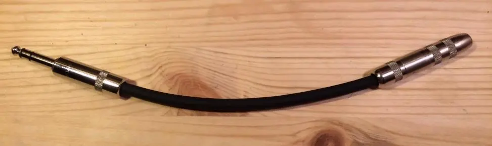
- Expression Pedal: Contains only one jack. Audio does not pass through it. It is connected using a 3-conductor 1/4 inch TRS cable. Its function is to control internal parameters of the connected equipment, which must be assigned via the equipment's user interface.
How Expression Pedals Work
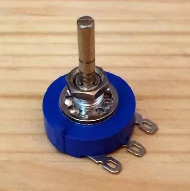
An expression pedal generally contains a single electrical component: a potentiometer (a variable resistor). As the pedal is moved, the shaft rotates, changing the resistance. This resistance is then interpreted by the connected equipment to adjust a specific parameter.
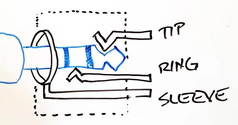
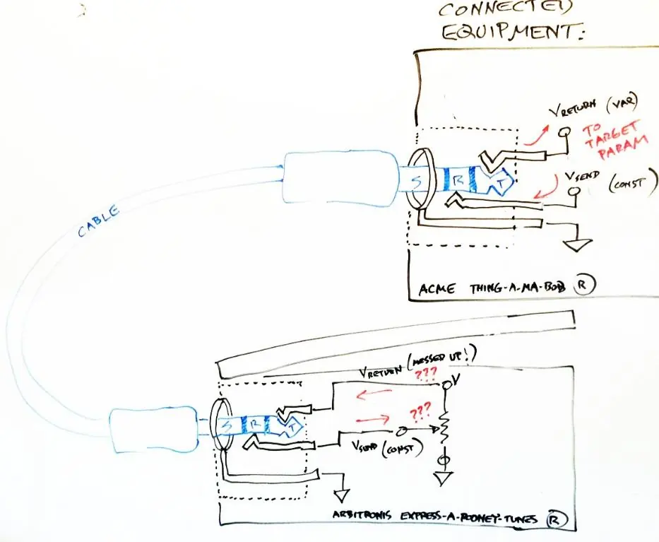
TRS Wiring and Connections
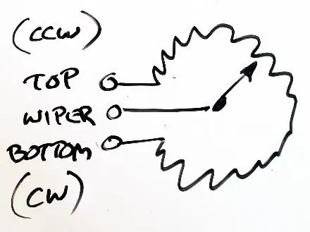
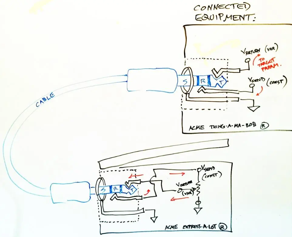
The "tricky part" of using expression pedals is the wiring. There are three connections involved: Tip, Ring, and Sleeve (TRS). Different manufacturers wire their pedals differently. The most common scheme involves the potentiometer's wiper connected to the Tip of the TRS cable. Some pedals, such as the Yamaha FC-7, use a different scheme where the wiper is connected to the Ring. If you encounter compatibility issues, you may need an adapter cable to swap these connections.
Compatibility and Troubleshooting
Because there is no universal standard for expression pedal wiring or resistance, users must verify compatibility:
- Resistance: Most pedals use a 10k ohm potentiometer. If your pedal has a higher resistance (e.g., 20k), the parameter may hit its maximum value before the pedal reaches the end of its travel.
- Calibration: If your equipment supports it, use a calibration function to synchronize the pedal's physical range with the target parameter's range.
- Taper: Expression pedals typically use linear-taper potentiometers. Using an audio-taper potentiometer (common in volume pedals) may result in uneven control, where the parameter changes rapidly in one part of the pedal's travel and slowly in another.
- Wiring Mismatch: If a pedal is incompatible, it may not work at all or could potentially cause a short. Always check the manufacturer's specifications for the required wiring scheme.
Manufacturer information
Yamaha
Practical help
Common problems
Parameter hits maximum value too early
The pedal's maximum resistance is likely higher than what the equipment expects. Use a calibration function if available.
Parameter does not reach full range
The pedal's resistance may be too low. Use a calibration function to synchronize the range.
Pedal does not work at all
Check for a wiring mismatch. Some pedals use a 'wiper-to-ring' scheme while others use 'wiper-to-tip'. You may need an adapter cable.
Before use
- Verify if your pedal is a Volume or Expression pedal.
- Ensure you are using a 3-conductor 1/4 inch TRS cable for expression pedals.
- Check the manufacturer's documentation for the required wiring scheme (Tip vs. Ring).
- Confirm if your equipment supports calibration for different pedal resistances.
Specs in practice
- Potentiometer
- The internal variable resistor that changes resistance based on pedal position.
- Linear Taper
- A type of potentiometer where resistance changes consistently across the entire rotation.
Images and diagrams
- TRS Wiring Diagram: Illustrates how the Tip, Ring, and Sleeve connections are wired between the pedal and the equipment.
- Potentiometer Schematic: Shows the variable resistor and the wiper connection.
Model compatibility
- Not all expression pedals are compatible with all equipment due to varying wiring schemes.
- Some equipment may require a specific resistance value (e.g., 10k ohm).
- Using an audio-taper potentiometer in an expression pedal may cause uneven control response.

Manual page author
Michael Turner
Technical manual editor
Reviews PDF manuals for structure, safety notes, and practical product details so readers can find the right information quickly.