Electronics / PA Systems
Service Manual for Yamaha DSP-AX1/RX-V1 AV Receiver
Comprehensive service manual for the Yamaha DSP-AX1 and RX-V1 AV receivers. Includes disassembly procedures, self-diagnosis functions, adjustment instructions, schematic diagrams, and parts lists.
Table of contents
Manual images
Click an image to enlargeImportant Service Information
This manual is intended for authorized Yamaha service personnel. Before servicing, observe the following safety precautions:
- Static Discharge: Static electricity can destroy expensive components. Always ground yourself to the unit's ground buss (heavy gauge black wires) before handling internal components.
- Power Off: Always turn the unit OFF during disassembly and part replacement. Recheck all work before applying power.
- Lead Solder: The solder used in this product contains lead. Avoid inhaling fumes and wash hands thoroughly after contact.
- Leakage Current: For 120V models, verify that all exposed conductive surfaces are properly insulated from supply circuits after service.
Disassembly Procedures
Follow these steps to access internal components:
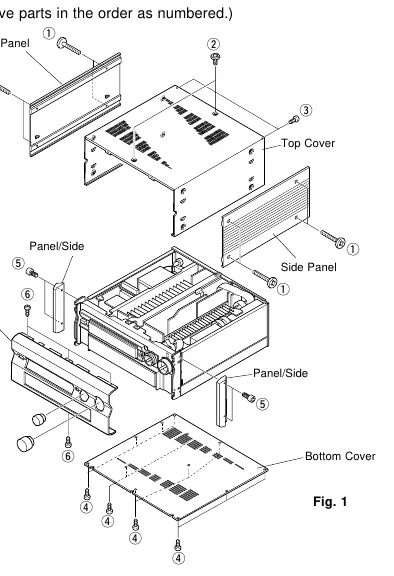
- Top Cover: Remove 8 screws to slide off the side panels, then remove 2 screws and 2 screws to lift the top cover.
- Bottom Cover: Remove 12 screws to detach the bottom cover.
- Front Panel: Remove 2 knobs, then remove 4 screws to slide the panel/side forward. Finally, remove 4 screws to detach the front panel.
Self-Diagnosis Function (DIAG)
The unit features a built-in self-diagnosis function to identify faulty items. To enter DIAG mode:
- DSP-AX1: Press the POWER key while holding the SET MENU+ and NEXT keys.
- RX-V1: Press the POWER key while holding the PROGRAM and EFFECT keys.
The diagnostic menu allows you to check various functions, including DSP, Decoder, RAM, Pro Logic, Speaker settings, and more. If the protection function is activated, you can enter the protection cancel mode to facilitate troubleshooting.
Adjustments
The manual provides detailed procedures for:
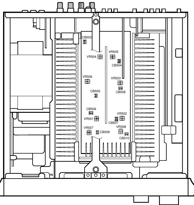
- Idling Current Adjustment: Wait 10 minutes with no signal after power-on. Use the specified test points (e.g., CB503-CB510) and adjustment points (VR501-VR508) to set the DC voltage to the specified rating.
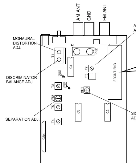
- Tuner Adjustments (RX-V1 only): Includes FM discriminator balance, monaural/stereo distortion, sensitivity, and AM sensitivity adjustments using a signal generator and oscilloscope.
Technical Specifications
The manual includes comprehensive specifications for the Audio and Video sections, including power output, frequency response, input sensitivity, and signal-to-noise ratios. It also provides detailed IC data, block diagrams, and schematic diagrams for all circuit boards.
Manufacturer information
Yamaha
Practical help
Common problems
Protection function activated
Use the self-diagnosis function (DIAG) to identify the fault (e.g., I PROTECTION, PS PRT, DC PRT, TMP PRT).
Incorrect key operation
Check the partial pressure resistor and soldering condition using the KY0/KY1 self-diagnosis menu.
No sound or distorted sound
Check idling current adjustment (AMP ADJUSTMENTS) and signal path using the DIAG menu.
Before use
- Ensure the unit is powered off before disassembly.
- Use an insulating table for leakage current measurement.
- Ground yourself to the unit's ground buss to prevent static damage.
- Write down existing tuner preset memory before resetting RAM.
Specs in practice
- Minimum RMS Output Power
- 110W+110W (Main, 20Hz-20kHz, 0.015% THD, 8Ω).
- Damping Factor
- 200 or more (Main/Center, 20Hz-20kHz, 8Ω).
- Video Signal-to-Noise Ratio
- 50dB.
Images and diagrams
- Internal view showing component locations.
- Disassembly diagrams for top cover, bottom cover, and front panel.
- Self-diagnosis menu flowcharts.
- Schematic diagrams for main, video, and tuner sections.
Model compatibility
- Specifications vary by model (U, C, A, B, G, R, T).
- Some adjustments (Tuner) apply only to RX-V1.

Manual page author
Emily Carter
User documentation editor
Prepares concise manual descriptions and highlights the most useful setup, operation, and maintenance information for readers.