Electronics / Monitors
User Manual for Yamaha B000UJHIS8 Expression Pedal
A comprehensive guide to understanding expression pedals, their circuitry, wiring standards, and compatibility. Learn how to troubleshoot connection issues, calibrate your pedal, and understand the differences between volume and expression...
Table of contents
Manual images
Jump to the sectionQuick guide from the manual
This document serves as an educational guide for understanding expression pedals. It explains the fundamental differences between volume and expression pedals, details internal circuitry (potentiometers), and provides essential information on wiring standards and compatibility. If you are experiencing issues with your pedal not controlling parameters correctly, check the wiring scheme of your specific pedal model and ensure it matches your equipment's input requirements.
Understanding Expression Pedals
An expression pedal is a data entry device used to control internal parameters of electronic equipment like keyboards or stomp boxes. Unlike a volume pedal, which passes audio signals through itself, an expression pedal does not pass audio. It connects via a 3-conductor 1/4 inch TRS cable to a dedicated expression pedal input.
Expression Pedal Circuitry
The core component of an expression pedal is a potentiometer (a variable resistor). As the pedal moves, the potentiometer shaft rotates, changing the resistance. The pedal's function is determined by how this potentiometer is wired to the TRS connector. Common variations include:
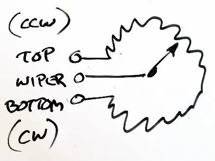
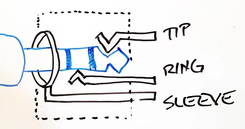
- Wiper-to-Tip: The most common wiring scheme where the potentiometer wiper is connected to the Tip of the TRS cable.
- Wiper-to-Ring: A less common scheme (used by pedals like the Yamaha FC-7) where the wiper is connected to the Ring.
Calibration and Compatibility
If your pedal does not reach the full range of a target parameter, or hits the maximum value too early, it may require calibration. For devices like the ControllerHub 8, you can use the Calibrate function to accommodate different potentiometer resistances (up to 100k ohm). Calibration synchronizes the pedal's physical travel (heel-down to toe-down) with the equipment's parameter range.
Troubleshooting
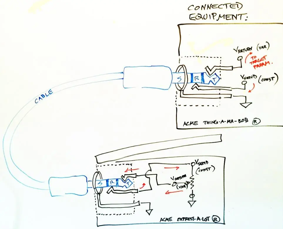
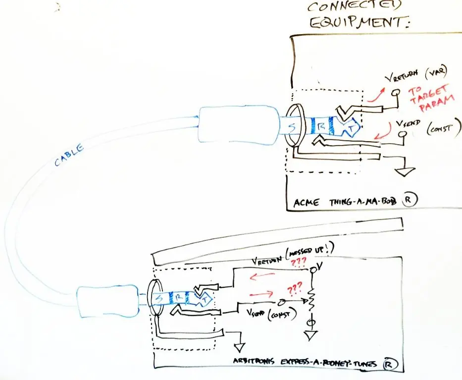
If you connect a pedal with a different wiring scheme than what your equipment expects, the pedal may not function, or there is a risk of shorting the equipment's send voltage to ground. If you encounter compatibility issues, you may need an adapter cable to swap the Tip and Ring connections. Always avoid using the extreme ends of pedal travel when testing for compatibility to prevent potential shorts.
Manufacturer information
Yamaha
Practical help
Common problems
Target parameter hits maximum value before the pedal reaches the toe-down position.
The pedal's potentiometer resistance is higher than the equipment's default setting. Perform a calibration procedure to synchronize the pedal range.
Pedal does not control the parameter at all.
Check if the pedal's wiring scheme (Wiper-to-Tip vs. Wiper-to-Ring) matches your equipment's input. You may need an adapter cable to reverse the Tip and Ring connections.
Pedal has 'fast' and 'slow' ranges, making control feel uneven.
This is likely due to an audio-taper potentiometer being used in an expression pedal. If possible, use a pedal with a linear-taper potentiometer for smoother control.
Before use
- Verify if your equipment requires a 1/4 inch TRS cable for the expression pedal.
- Check if your pedal uses a linear-taper or audio-taper potentiometer.
- Confirm the wiring scheme of your pedal (Wiper-to-Tip or Wiper-to-Ring).
- Ensure the equipment's expression input is correctly assigned to the desired parameter.
- If using multiple pedals, consider the weight and construction material for stability.
Specs in practice
- Potentiometer
- A variable resistor that changes resistance based on shaft rotation; the primary component of an expression pedal.
- Linear Taper
- A potentiometer type where resistance changes at a constant rate; preferred for expression pedals.
Images and diagrams
- The manual provides diagrams showing the internal wiring of TRS connectors and how they interface with the potentiometer.
- Schematic symbols illustrate how the potentiometer wiper splits the total resistance into two variable parts (R1 and R2).
Model compatibility
- Not all expression pedals are compatible with all equipment due to varying wiring schemes.
- The ControllerHub 8 is designed to be compatible with the most common 'Wiper-to-Tip' wiring scheme.
- An adapter cable is available for pedals using the 'Wiper-to-Ring' scheme, such as the Yamaha FC-7.

Manual page author
Michael Turner
Technical manual editor
Reviews PDF manuals for structure, safety notes, and practical product details so readers can find the right information quickly.