Plumbing / Sump Pumps
Zoeller 1105528B-VM3 Vertical Pump Switch Installation Instructions
Quick installation guide for the Zoeller 1105528B-VM3 Vertical Pump Switch. Includes wiring diagrams, pumping range adjustments, and essential safety warnings for proper operation.
Table of contents
Quick guide from the manual
The Zoeller 1105528B-VM3 is a mechanically activated vertical pump switch designed for direct control of pumps in non-potable water applications. It is intended for pump-down applications only.
- Pumping Range: 2 to 6.5 inches (5 to 17 cm).
- Max Temperature: 140°F (60°C).
- Load Requirement: Must switch loads greater than 1 Amp at 120 VAC. Not suitable for pilot duty (control) applications.
Safety Warnings
Electrical Shock and Explosion Hazard: Disconnect power before installing or servicing. Do not use with flammable liquids. Install in accordance with National Electric Code, ANSI/NFPA 70. Ensure all cable connections are performed in a dry junction box or watertight seal to prevent moisture entry.
Installation
- Determine Location: Identify the appropriate location for the float switch.
- Secure Switch: Attach the switch to the discharge pipe by inserting the hose clamp through the mounting bracket slots and tightening it.
- Adjust Range: The pumping range can be adjusted by adding a second clip or stopper to the rod.
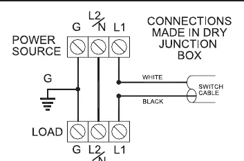
- Wiring (Units without plugs): Connect wires as shown in the wiring diagram. Ensure connections are made in a dry junction box.
- Test: Always test the unit after installation to ensure proper operation.
Maintenance
- Periodically inspect the cable for wear or damage to the housing. Replace immediately if damaged.
- Check that the float and rod are free to move and operate the switch.
- Use only approved replacement parts.
Practical help
Common problems
Switch fails prematurely
Ensure the load is greater than 1 Amp at 120 VAC. This switch is not suitable for pilot duty (control) applications.
Electrical shock hazard
Ensure all cable connections are performed in a dry junction box or watertight seal to prevent moisture from entering the switch.
Before use
- Verify pumping range requirements (2 to 6.5 inches)
- Check that the float and rod move freely
- Ensure power is disconnected before installation
- Confirm load is greater than 1 Amp at 120 VAC
Specs in practice
- Pumping Range
- The distance the water level must rise or fall to activate or deactivate the pump (2 to 6.5 inches).
- Max Operating Temperature
- The maximum liquid temperature the switch can withstand (140°F / 60°C).
Images and diagrams
- The wiring diagram shows connections for units without plugs, requiring a dry junction box.
- The installation steps illustrate securing the switch to the discharge pipe using a hose clamp.
Model compatibility
- Designed for pump down applications only.
- Not suitable for pilot duty (control) applications.

Manual page author
Michael Turner
Technical manual editor
Reviews PDF manuals for structure, safety notes, and practical product details so readers can find the right information quickly.