Electronics / Networking
User Manual for StarTech.com 1-Port RS232 Serial Over IP Device Server
Quick setup and configuration guide for the StarTech.com 1-Port RS232 Serial Over IP Device Server. Includes hardware installation, software setup, Telnet configuration, and LED status indicators.
Table of contents
Manual images
Click an image to enlargeQuick Start Guide
The StarTech.com 1-Port RS232 Serial Over IP Device Server allows you to connect serial devices to a network. Note that the device can take up to 80 seconds to startup after power is applied. For initial setup, download the software package from the StarTech.com website, connect the device to your network via Ethernet, and use the Device Server Manager to discover and configure the unit.
Product Overview
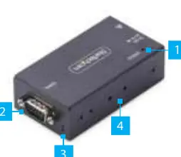
Front View: Features a Status LED, a DB-9 Serial Port for connecting your RS-232 device, Serial Communication LED indicators, and mounting bracket holes for DIN rail or wall installation.
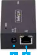
Rear View: Contains the DC Power Input and the Ethernet Port. The I13P-SERIAL-ETHERNET model supports 802.3af Power over Ethernet (PoE).
Hardware Installation
Optional DB-9 Pin 9 Power Configuration: By default, the device is configured with the Ring Indicator (RI) on Pin 9. To change this to 5V DC output:
- Ensure the device is disconnected from power and peripherals.
- Use a Phillips screwdriver to remove the housing screws.
- Carefully open the housing to expose the circuit board.
- Locate Jumper #4 (JP4) next to the DB9 connector.
- Move the jumper to the 5V position.
- Re-assemble the housing.
Mounting: The device can be mounted using a DIN Rail or Wall Mount bracket. Secure the bracket to the device using the included screws, then attach it to your chosen surface.
Software Installation
The StarTech.com Device Server Manager is required for configuration and is supported on Windows operating systems.
- Navigate to the product support page on the StarTech.com website.
- Download the Software Package for Windows.
- Extract the .zip file and run the executable to install.
- Launch the manager and click Auto Search to discover the device on your local network.
Operation and Configuration
Telnet: You can communicate with the connected serial peripheral via Telnet using any OS. Simply connect to the device's IP address via a terminal or command prompt.
Serial Port Settings: You can configure settings such as Baud Rate (300 to 921600), Data Bits (7 or 8), Parity (None, Even, Odd, Mark, Space), Stop Bits (1 or 2), and Flow Control via the Device Server Manager or the Web Interface.
Changing COM Port/Baud Rate: If you need to change these settings in Windows, you must delete the device in the Device Server Manager, modify the settings via the web interface, and then re-add the device in the manager.
LED Indicators
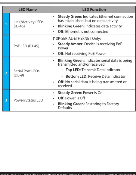
- Link/Activity LEDs (RJ-45): Steady Green indicates connection; Blinking Green indicates data activity.
- PoE LED (RJ-45): Steady Amber indicates PoE power is being received (I13P model only).
- Serial Port LEDs (DB-9): Blinking Green indicates serial data transmission/reception.
- Power/Status LED: Steady Green indicates power is on; Blinking Green indicates restoring to factory defaults.
Official resources from the manual
Practical help
Common problems
Device not discovered by software
Ensure the device is connected to the same local network and click 'Auto Search' in the Device Server Manager.
PoE not working (I13P model)
Ensure the device is connected to a Power Sourcing Equipment (PSE) switch or injector.
COM port conflict
Ensure the assigned COM port number is not already in use by another system process.
Before use
- Ensure you are properly grounded before opening the device housing.
- Verify the power source (PoE or included power adapter).
- Download the latest software package from the StarTech.com website.
- Ensure the Ethernet cable is connected to a router, switch, or hub.
Images and diagrams
- Front View: Identifies the Status LED, DB-9 Serial Port, Serial Communication LEDs, and Mounting Bracket Holes.
- Rear View: Identifies the DC Power Input and Ethernet Port.
Model compatibility
- Device Server Manager software is only supported on Windows operating systems.
- I13P-SERIAL-ETHERNET supports 802.3af PoE.
- If PoE is unavailable for the I13P model, a 5V, 3A+ Type M power adapter is required.

Manual page author
Emily Carter
User documentation editor
Prepares concise manual descriptions and highlights the most useful setup, operation, and maintenance information for readers.