Furniture / Storage Cabinets
User Manual for Secomp 1000BaseSX Series Media Converter
Quick installation guide for the Secomp 1000BaseSX Series Media Converter. Includes setup instructions, LED indicators, LLF/LFP function details, and technical specifications.
Table of contents
Manual images
Click an image to enlargeQuick guide from the manual
The Secomp 1000BaseSX Series Media Converter is designed to bridge 10/100/1000BaseT(X) signals to 1000BaseSX/LX signals. It allows for extending connection distances between two Gigabit Ethernet twisted-pair devices via fiber cable without performance degradation. Before starting, ensure your package contains the Media Converter, Power Adapter, and the Quick Installation Guide.
Installation
Power Supply: The device requires an external power adapter with a DC input of +5VDC 2A.
TP Port: The TP port supports Auto-MDIX, Auto-Negotiation, and Flow Control. It is compatible with Cat5, Cat5e, or Cat6 shielded/unshielded twisted-pair cables up to 100 meters.
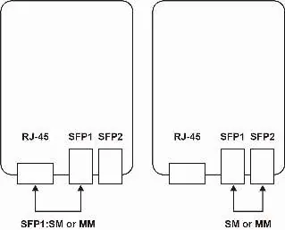
SFP Slots: The device features two SFP open slots that support both multi-mode and single-mode SFP modules.
LED Indicators
The device includes LED indicators to monitor status:
- Power: On when the device is powered.
- TX: Flashing when the port is transmitting data.
- RX: Flashing when the port is transmitting data.
- LINK: On when the port is connected.
LLF/LFP Function
Link Loss Forwarding (LLF) / Link Fault Pass Through (LFP) is a function designed to pass the message if an optical fiber link fails. This allows system administrators to notice link failures within a short period, minimizing downtime.
Technical Specifications
- Standards: IEEE 802.3 10BaseT, 802.3u 100BaseTX, 802.3ab 1000BaseT, 802.3z 1000BaseSX/LX, 802.3x Flow Control.
- Data Transfer Rate: 20/200/2000Mbps/Full-Duplex.
- Power Requirement: DC5V/2A.
- Power Consumption: 10 Watts (Max).
- Dimensions: 102 x 74 x 22 mm.
- Operating Temperature: 0 to 45°C.
- Humidity: 10 to 90% RH (non-condensing).
Connection Diagrams
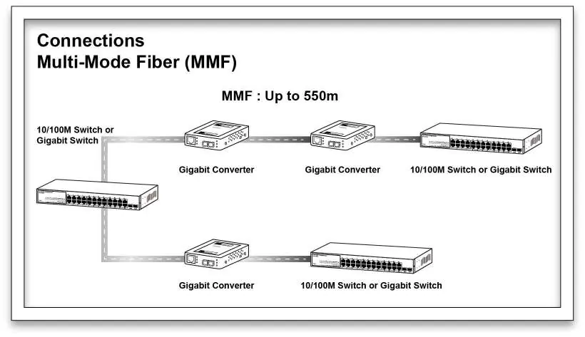
The converter supports different connection setups depending on the fiber type used (Multi-Mode or Single-Mode). Ensure the correct fiber optic cable is used for the specific SFP module installed.
Practical help
Common problems
Link failure not detected
Ensure the LLF/LFP function is enabled to allow the system to pass link fault messages to administrators.
Device not powering on
Verify that the external power adapter is securely connected and providing the required +5VDC 2A.
Before use
- Verify package contents: Media Converter, Power Adapter, and Quick Installation Guide.
- Ensure you have the appropriate SFP modules (Multi-mode or Single-mode).
- Use Cat5, Cat5e, or Cat6 shielded/unshielded twisted-pair cables for the TP port.
- Check that the power source provides +5VDC 2A.
Specs in practice
- Power Requirement
- Requires a stable +5VDC 2A power input.
- Operating Temperature
- The device should be operated in environments between 0°C and 45°C.
- Transmission Media
- Supports Cat5/5e/6 for TP connections and fiber optic cables for SFP connections.
Images and diagrams
- LLF/LFP Function: Illustrates how the converter passes link fault messages when an optical fiber link goes down.
- Connection Diagrams: Shows the setup for Multi-Mode (MMF) and Single-Mode (SMF) fiber connections between switches.
Model compatibility
- Supports 10/100/1000BaseT(X) to 1000BaseSX/LX conversion.
- SFP slots support both multi-mode and single-mode modules.

Manual page author
Michael Turner
Technical manual editor
Reviews PDF manuals for structure, safety notes, and practical product details so readers can find the right information quickly.