Electronics / Networking
User Manual for Fortinet FortiGate 1000D Network Security Device
Quick guide for the Fortinet FortiGate 1000D network security device. Includes installation instructions for rack and desktop setups, LED indicator status meanings, port layout, and safety warnings.
Table of contents
Manual images
Click an image to enlargeQuick guide from the manual
The FortiGate 1000D is a network security device. The box includes the unit, two power cables, console cable, USB cable, Ethernet cable, two rack-mount brackets, 12 bracket screws, two grounding screws, and four rubber feet. Ensure the device is installed in a clean, level, and stable environment with adequate airflow.
Device Overview
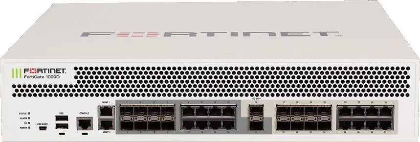
The front panel features various ports and status indicators:
- SFP Ports: SFP+ (10Gbps) and SFP (1Gbps) ports for network connectivity.
- Ethernet Ports: RJ-45 ports for Gigabit Ethernet network connections.
- Management Ports: MGMT 1 and MGMT 2 (RJ-45) for management. The default IP address for MGMT 1 is 192.168.1.99.
- Console Port: RJ-45 connection for CLI access.
- USB Ports: USB (Type A) server port and USB MGMT (Type B) client port.
LED Indicators
Monitor the device status using the front panel LEDs:
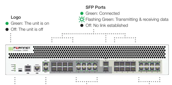
- Status: Green (Normal), Flashing Green (Booting up), Red (Major alarm).
- Alarm: Red (Critical error), Amber (Minor error), Off (No errors).
- HA: Green (Normal), Red (Failover), Off (Disabled).
- Power: Green (On), Off (Off).
- SFP/Ethernet Ports: Green (Connected), Flashing Green (Transmitting/Receiving), Off (No link).
- Power Supplies: Green (Providing power), Flashing Green (Functional but not providing power), Red (Failed), Flashing Red (Not powered).
Installation
Rack Installation
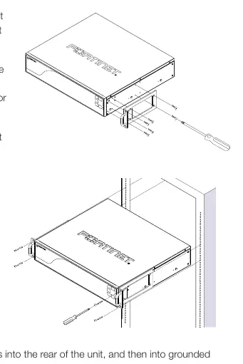
- Attach the provided rack-mount brackets to the sides of the unit using the provided screws.
- Position the unit in a standard 19-inch rack. Ensure sufficient room for air flow.
- Line up the bracket holes with the rack holes and ensure the unit is level.
- Finger tighten four rack-mount screws to attach the unit.
- Verify spacing and level, then tighten the screws with a screwdriver.
- Plug power cables into the rear of the unit and then into grounded outlets or UPS/PDU.
Desktop Installation
- Ensure the surface is clean, level, and stable.
- Attach the provided rubber feet to the bottom of the unit.
- Place the unit in the designated location, ensuring at least 1.5 inches (3.8cm) of clearance on all sides for airflow.
- Plug the power cables into the rear of the unit and then into grounded outlets.
Safety and Warnings
- Electrostatic Discharge (ESD): ESD can damage equipment.
- Airflow: Do not block air vents; ensure adequate clearance.
- Power: Use redundant power supplies as provided. Disconnect all power sources before servicing.
- Battery: Risk of explosion if the battery is replaced by an incorrect type. Dispose of used batteries according to local regulations.
- Environment: Ambient operating temperature is 0°C to 40°C.
Manufacturer information
Fortinet, Inc.
Practical help
Common problems
Alarm LED is Red
Indicates a critical error. Check system logs for details.
Alarm LED is Amber
Indicates a minor error. Check system logs for details.
Power supply LED is flashing red
The power supply has failed or is not powered. Check power connections.
Before use
- Ensure the installation surface is clean, level, and stable.
- Verify at least 1.5 inches (3.8cm) of clearance on all sides for airflow.
- Use grounded electrical outlets or UPS/PDU.
- For rack installation, use two or more people to lift the unit.
- Do not place heavy objects on the unit.
Specs in practice
- MGMT 1 Default IP
- 192.168.1.99
- Operating Temperature
- 0°C to 40°C
Images and diagrams
- Front panel diagram identifies SFP, Ethernet, Management, Console, and USB ports.
- Rear panel diagram shows redundant power supply locations.
Model compatibility
- Compatible with standard 19-inch rack units.

Manual page author
Michael Turner
Technical manual editor
Reviews PDF manuals for structure, safety notes, and practical product details so readers can find the right information quickly.