Electronics / Networking
Installation Guide for TP-Link 1000Base-BX WDM SFP Module
A comprehensive installation and setup guide for TP-Link 1000Base-BX WDM Bi-Directional SFP Modules. Includes step-by-step instructions for installation and removal, connection diagrams, technical specifications, and safety precautions.
Table of contents
Quick Guide for SFP Module Installation
This guide covers the installation and removal of TP-Link 1000Base-BX WDM Bi-Directional SFP modules. Always use an ESD-preventive wrist or ankle strap during handling to prevent damage to the transceiver. Keep the protective dust plug on the optical bores until you are ready to make a connection.
Installation and Removal
To install the SFP module:
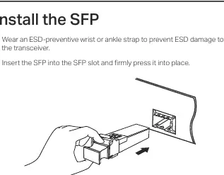
- Wear an ESD-preventive wrist or ankle strap.
- Insert the SFP module into the SFP slot and press it firmly into place.
- Remove the protective dust plug from the SFP.
- Plug the fiber-optic cable into the SFP. The module works without additional configuration.
To remove the SFP module:
- Wear an ESD-preventive wrist or ankle strap.
- Disconnect the network fiber-optic cable from the SFP.
- Pull the safety latch downwards to release the SFP, then pull it out from the slot.
- Reinstall the protective dust plug into the optical bores and place the module on an antistatic mat or in a static shielding bag.
Connection
For reliable connectivity between switches, use the compatible pairs together (e.g., TL-SM321A with TL-SM321B, or TL-SM321A-2 with TL-SM321B-2). Connect the fiber-optic cable between the two switches using the SFP ports.
Specifications
The modules support IEEE 802.3z and TCP/IP standards with a data rate of 1.25 Gbps. Power support is 3.3 V. The operating temperature range is 0°C to 70°C (32°F to 158°F), and storage temperature is -40°C to 85°C (-40°F to 185°F).
Compatibility
These SFP modules are designed for use with TP-Link switches featuring gigabit SFP slots and the MC220L media converter. Note that the modules may be incompatible with other vendors' devices; it is recommended to use only TP-Link SFP modules on TP-Link devices.
Safety Information
Keep the device away from water, fire, humidity, or hot environments. Do not attempt to disassemble, repair, or modify the device. Avoid using the product during an electrical storm. Do not point or stare directly into the beam or into the optical port of the transceiver when it is operating, as this can cause eye injury.
Practical help
Common problems
ESD damage to the transceiver
Always wear an ESD-preventive wrist or ankle strap when handling the module.
Incompatibility with other vendors' devices
Use only TP-Link SFP modules on TP-Link devices to ensure compatibility.
Eye injury from laser beam
Do not point or stare directly into the beam or the optical port while the device is operating.
Before use
- Wear an ESD-preventive wrist or ankle strap.
- Verify the switch has a gigabit SFP slot.
- Ensure you have the correct pair of modules (e.g., A and B).
- Keep the protective dust plug on until ready to connect.
Specs in practice
- Max. Cable Length
- The maximum distance the signal can travel (2 km or 20 km depending on the model).
Images and diagrams
- The connection diagram illustrates a point-to-point fiber connection between two switches using a pair of compatible SFP modules.
Model compatibility
- Compatible with TP-Link switches with gigabit SFP slots.
- Compatible with MC220L media converter.
- Use TL-SM321A and TL-SM321B together.
- Use TL-SM321A-2 and TL-SM321B-2 together.

Manual page author
Michael Turner
Technical manual editor
Reviews PDF manuals for structure, safety notes, and practical product details so readers can find the right information quickly.