HVAC / Air Conditioners
Service Manual for ACiQ 18K-55K Multi-Zone Condenser
Comprehensive service manual for ACiQ 18K-55K Multi-Zone Condensers. Includes safety precautions for flammable refrigerants, technical specifications, indoor unit combination charts, wiring diagrams, disassembly procedures, and detailed...
Quick answers from the manual
Quick answer
- This service manual provides technical specifications, disassembly instructions, wiring diagrams, and troubleshooting procedures for ACiQ 18K-55K Multi-Zone Condensers. p. 1, 3
Key actions
- Disassemble outdoor unit p. 53, 55, 59
Problems and fixes
EC51 (EEPROM error)
Power off, wait 2 minutes, power on. If error persists, replace outdoor main PCB.
p. 102Error codes
| Code | Meaning | Action | Pages |
|---|---|---|---|
| EC51 | ODU EEPROM parameter error | Replace outdoor main PCB | p. 94, 102 |
| EL01 | IDU & ODU communication error | Check wiring and PCB connections | p. 94, 103 |
Maintenance and reset
- Press the 'check switch' on the outdoor unit PCB for 5 seconds until LED displays 'CE' to initiate automatic wiring/piping correction. p. 130
Technical specifications
| Parameter | Value | Meaning | Pages |
|---|---|---|---|
| Power Supply | 208/230V~, 60Hz, 1Phase | Standard electrical requirement | p. 12 |
Where to find it in the PDF
- Safety Precautions p. 6, 7, 8, 9
- Specifications p. 12, 13, 14, 15
- Outdoor Unit Disassembly p. 53, 54, 55, 56
- Troubleshooting p. 94, 95, 96, 97
Table of contents
Manual images
Click an image to enlargeImportant Information from the Manual
This service manual is intended for qualified technicians. It covers the ACiQ 18K-55K Standard and Extreme Heat Multi-Zone Condenser series. Key safety information includes handling A2L flammable refrigerants, which requires specific certification and precautions. Always ensure the power is disconnected and capacitors are discharged before performing any service or maintenance.
Safety Precautions
WARNING: This unit uses flammable refrigerant. Technicians must hold a valid certificate from an industry-accredited authority. Ensure the work area is well-ventilated and free of ignition sources. Use appropriate leak detection equipment suitable for flammable refrigerants.
Specifications
The manual provides detailed model reference tables, including capacity (Btu/h) and power supply requirements (208/230V~, 60Hz, 1Phase). It also outlines refrigerant pipe length and drop height requirements, as well as extensive indoor unit combination charts for each outdoor unit model.
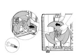
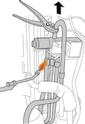
Outdoor Unit Disassembly
The manual provides step-by-step procedures for disassembling various outdoor unit models (X430, D30, E30). Procedures include:
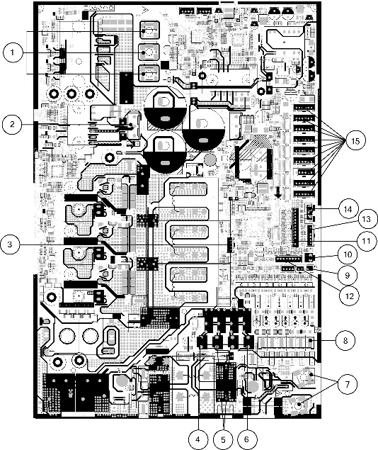
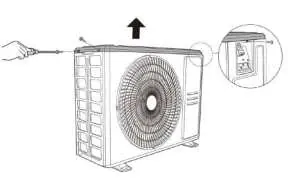
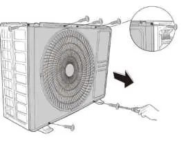
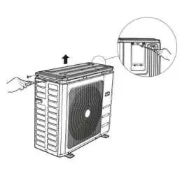
- Removing the panel plate and big handle assembly.
- Accessing and removing electrical parts, including the main control board and IPM board.
- Removing the fan assembly and fan motor.
- Removing the sound blanket.
- Detaching the four-way valve and compressor (requires brazing/soldering skills).
Troubleshooting
A comprehensive troubleshooting section is included, featuring:
- Error Display Table: A quick reference for identifying malfunctions based on the unit's display.
- Quick Maintenance: A table mapping error codes to specific parts requiring replacement.
- Diagnostic Flowcharts: Detailed step-by-step guides for diagnosing specific issues like communication errors, fan speed issues, and compressor protection.
Check Procedures
Technicians can perform specific checks to verify component health, including:
- Temperature Sensor Check: Measuring resistance and comparing it to the provided tables in the Appendix.
- Compressor Check: Measuring winding resistance.
- IPM Continuity Check: Verifying IPM health using a multimeter.
- Reactor and 4-Way Valve Checks: Testing for proper resistance and operation.
Manufacturer information
ACiQ
Practical help
Common problems
Communication error (EL01)
Check wiring between indoor and outdoor units, measure voltage between S and N, and verify indoor PCB connections.
Compressor overcurrent (PC49)
Check system pressure, ensure heat exchanger is clean, verify fan operation, and inspect reactor/inductance.
EEPROM parameter error (EC51)
Power off, wait 2 minutes, and power on. If the error persists, replace the outdoor main PCB.
Before use
- Ensure all power supplies are turned off before servicing.
- Wear antistatic gloves when handling electronic control boxes.
- Discharge all capacitors before troubleshooting.
- Verify refrigerant type and charge amount.
- Ensure proper ventilation when working with flammable refrigerants.
Specs in practice
- Power Supply
- 208/230V~, 60Hz, 1Phase for all models.
- Pipe Diameter
- Varies by indoor unit capacity (6k-36k) and requires specific adaptors for some outdoor units.
Images and diagrams
- Refrigeration cycle diagrams illustrate the flow of refrigerant through the system components.
- Electrical wiring diagrams detail the connections between the main control board, sensors, and motors.
Model compatibility
- T3B, T5, T6A, and T6B sensors are only applicable to hyper heat models.

Manual page author
David Miller
Documentation analyst
Organizes user manual content into clear summaries, with attention to model details, product context, and everyday usability.