HVAC / Air Conditioners
User Manual for ACiQ PTAC Heat Pump Air Conditioner
Quick guide for ACiQ PTAC Heat Pump. Includes installation, operation, dip switch settings, maintenance, and troubleshooting.
Table of contents
Manual images
Click an image to enlargeQuick guide from the manual
This manual provides installation, operation, and maintenance instructions for the ACiQ PTAC Heat Pump series. Key tasks include ensuring the unit is installed on a dedicated circuit, configuring dip switches for specific operational needs (such as wall thermostat control or temperature display units), and performing regular filter cleaning every two weeks to maintain efficiency.
Safety Precautions
- Always use a dedicated circuit and correctly rated breaker.
- Do not modify or extend the power cable.
- Ensure the unit is properly grounded.
- Do not install, remove, or reinstall the unit yourself; contact a qualified professional.
- Be cautious of sharp edges on the case and fins during installation.
Control Panel Operation
The control panel allows you to manage the unit's operation:
- Power: Turns the unit on or off.
- Mode: Cycles through COOL, HEAT, FAN, and COOL modes.
- Temperature (+/-): Adjusts the set temperature. Press and hold both for 3 seconds to toggle between Celsius and Fahrenheit.
- Fan Speed: Cycles through HIGH, MED, and LOW speeds.
- Constant Fan: Toggles continuous fan operation in cooling mode.
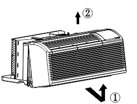
Installation Details
Proper installation is critical for performance and safety:
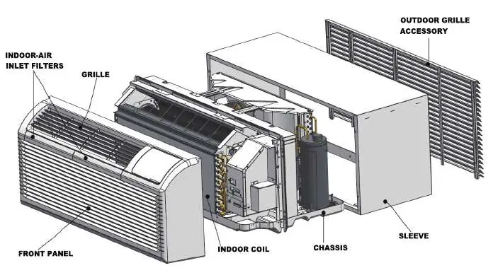
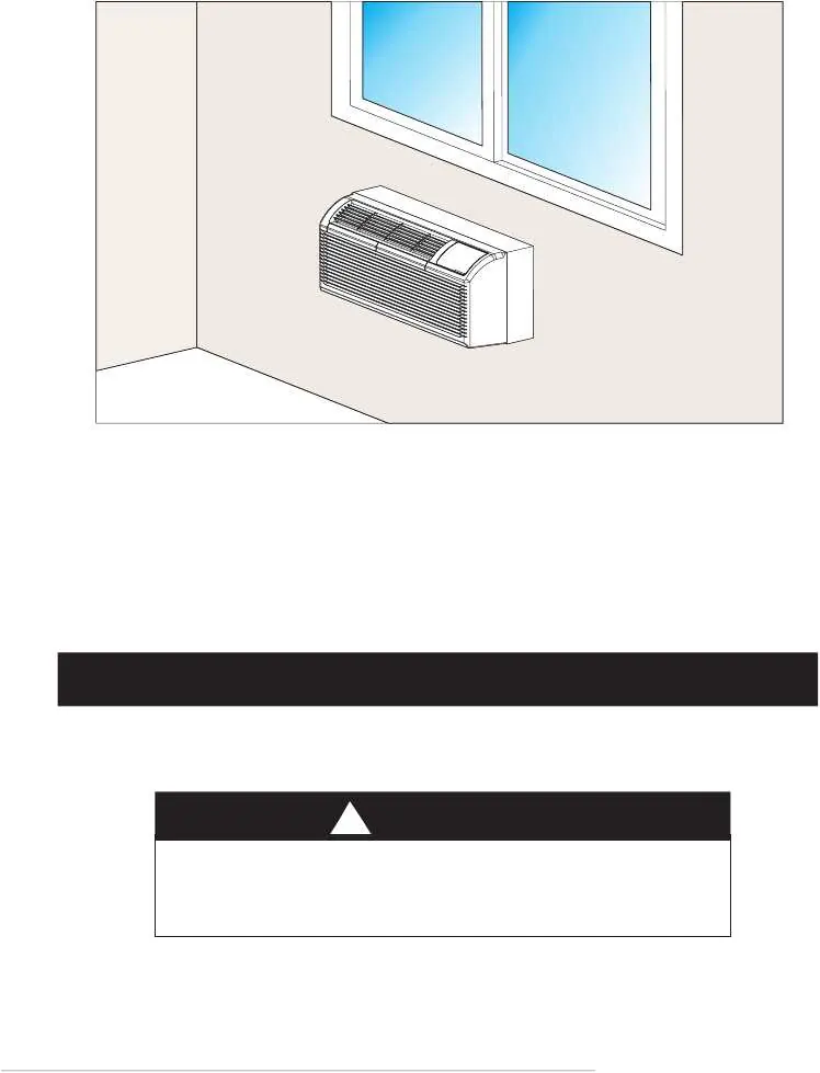
- Sleeve Preparation: Ensure the wall sleeve is in good structural condition and level to prevent vibration and water leakage.
- Unit Installation: Slide the unit into the sleeve until it is firmly against the front. Secure with 4 screws and washers through the flange holes.
- Vent Control: Use the vent control lever to open or close the vent door. Note that setting it to OPEN allows outdoor air into the room, which may reduce heating or cooling efficiency.
Dip Switches Configurations
The unit features optional dip switches located behind the front panel for advanced configuration:
- S1: Selects Electric Heat Only or Electric Heat and Pump Heat.
- S2: Toggles temperature display between Celsius and Fahrenheit.
- S3: Enables Wall Thermostat or Control Panel.
- S6/S7: Configures fan operation (Continuous or Cycle) for heating and cooling.
- S8: Enables or disables low-temperature protection.
Care and Cleaning
Regular maintenance is essential for unit longevity:
- Filters: Clean every two weeks. Vacuum heavy soil and run water through the filter. Dry thoroughly before replacing.
- Outdoor Coil: Check regularly for dirt and soot buildup. If clogged, have it professionally cleaned. Never use high-pressure spray.
- Front Panel: Clean with a soft cloth and mild detergent. Avoid bleach or abrasives.
Troubleshooting
If the unit displays an error code, try unplugging it and plugging it back in. If the error persists, contact service. Common codes include:
- AS/ES/CS/oS/HS: Temperature sensor open or short circuit.
- E4: Communication malfunction between main control board and display board.
- LE: Drive-by-wire controller failure.
- LO/HI: Room temperature is outside the display range.
Manufacturer information
ACiQ
Practical help
Common problems
Unit does not start
Check if the plug is secure, the test/reset button on the plug has not tripped, the circuit breaker is on, or the unit is in a protection mode.
Unit not cooling/heating
Check for blocked airflow, dirty filters, or if the vent door is open. Verify dip switch settings.
Water dripping inside
Ensure the wall sleeve is installed level to allow proper drainage.
Ice or frost on indoor coil
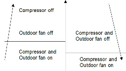
Occurs when outdoor temperature is approx 55°F or below. Switch to FAN mode until ice melts.
Before use
- Ensure the unit is on a dedicated circuit.
- Verify the wall sleeve is level and in good condition.
- Check that the power plug is secure and not tripped.
- Ensure filters are clean and properly installed.
- Verify vent control lever is set to the desired position (Closed for efficiency).
Specs in practice
- Input Voltage
- 230/208V, 60Hz.
- Cooling Temp Range
- 17°C/62°F to 30°C/86°F.
- Heating Temp Range
- 17°C/62°F to 29°C/84°F.
Images and diagrams
- Wiring Diagram: Shows connections for power, fan, compressor, and optional wall thermostat.
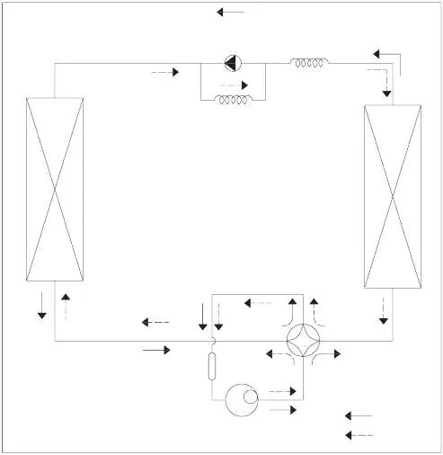
- Refrigerant Cycle: Illustrates the flow of refrigerant through the compressor, heat exchangers, and valves.
- Dip Switches: Visual guide for configuring operational settings like thermostat control and temperature units.
Model compatibility
- Wall thermostat must be a heating changeover 4-way valve type.
- 265V models require an accessory electrical subbase.
- Some features (like front desk control) require specific dip switch settings.

Manual page author
Michael Turner
Technical manual editor
Reviews PDF manuals for structure, safety notes, and practical product details so readers can find the right information quickly.