HVAC / Air Conditioners
Installation Manual for ACiQ Outdoor Unit Central Inverter Systems
Comprehensive installation guide for ACiQ outdoor inverter units. Includes safety precautions, refrigerant piping, wiring diagrams, evacuation procedures, and test run instructions.
Quick answers from the manual
Quick answer
- This manual provides installation instructions for ACiQ outdoor inverter units. It covers safety, piping, wiring, evacuation, and test run procedures. Installation must be performed by a licensed professional. p. 1, 3
Key actions
- Install the unit on a firm, level surface. p. 13, 15
- Perform vacuum evacuation. p. 21
- Connect wiring according to the diagram. p. 18, 19, 20
First start
- Perform a test run after installation. p. 23
Problems and fixes
Abnormal situation (burning smell)
Turn off the unit and disconnect power immediately.
p. 5Technical specifications
| Parameter | Value | Meaning | Pages |
|---|---|---|---|
| Power Supply | 208/230V, 60Hz | Standard operating voltage for the units. | p. 22 |
Where to find it in the PDF
- Safety Precautions p. 4, 5, 6
- Outdoor Unit Installation p. 13, 15, 16
Table of contents
Manual images
Click an image to enlargeQuick guide from the manual
This manual provides essential installation instructions for ACiQ outdoor inverter systems. Installation must be performed by a licensed professional HVAC installer or equivalent. Improper installation can lead to property damage, personal injury, or loss of life. Always ensure the unit is properly grounded and installed on a firm, level surface.
Safety Precautions
Before beginning installation, read all safety guidelines carefully:
- Electrical Safety: Use a dedicated electrical circuit. Ensure the unit is properly grounded. Turn off the main power before performing any electrical work.
- Handling: Use two or more people to move the unit to avoid injury. Wear gloves and protective clothing to avoid sharp sheet metal edges.
- Environment: Do not install in locations exposed to combustible gas leaks, excessive dust, or where the unit may be exposed to heavy rain or snow without protection.
Outdoor Unit Installation
Select a location that meets the following requirements:
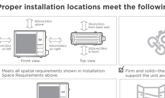
- Space: Ensure adequate clearance for air circulation (refer to the installation space requirements diagram).
- Support: The location must be firm and solid to support the unit's weight and prevent vibration.
- Drainage: Install the unit on risers of at least 15cm (6in) to keep it above local mean snowfall.
- Extreme Weather: If exposed to heavy wind, install the outlet fan at a 90° angle to the wind direction. If exposed to heavy rain or snow, build a shelter above the unit.
Refrigerant Piping Connection
Proper piping is critical for system efficiency:
- Cutting: Use a pipe cutter to ensure a perfect 90° angle. Remove all burrs to prevent leaks.
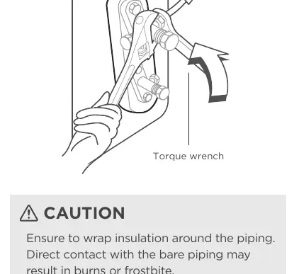
- Flaring: Proper flaring is essential for an airtight seal. Use a torque wrench to tighten flare nuts according to the specified torque values.
- Oil Traps: Install an oil trap every 6m (20ft) for units <36,000 Btu/h or every 10m (32.8ft) for units ≥36,000 Btu/h on vertical suction line risers.
Wiring
All electrical connections must follow the wiring diagram located on the panels of the indoor and outdoor units:
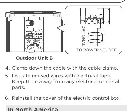
- Connection Methods: The manual details specific methods (A, B, C) depending on the control system (communicating vs. 24V thermostat).
- DIP Switches: Configure DIP switches on the outdoor unit according to the required features (e.g., 24V communication scheme vs. 485 communication scheme).
- Cabling: Do not intertwine signal cables with other wiring.
Air Evacuation
Evacuation is required to remove non-condensable gas and moisture:
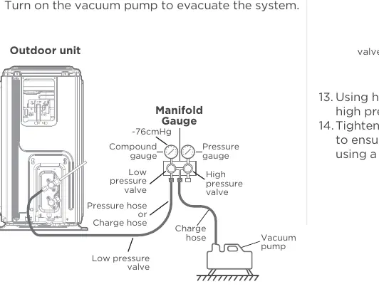
- Connect the manifold gauge to the outdoor unit's low-pressure valve and the vacuum pump.
- Run the vacuum pump until the compound meter reads -76cmHg or 500 microns.
- Wait 5 minutes to ensure no pressure change.
- Open the high and low-pressure valves using a hexagonal wrench.
Test Run
Perform a test run after installation is complete:
- Verify that the refrigeration system does not leak.
- Check that the drainage system is unimpeded.
- Ensure there is no abnormal noise or vibration during operation.
- Confirm the unit is operating in the correct mode (e.g., COOL mode).
Manufacturer information
ACiQ
Practical help
Common problems
Unit not starting or abnormal operation
Check power supply, wiring connections, and ensure the unit is properly grounded.
Refrigerant leakage
Ensure all piping connections are tight and properly flared. Perform a leak check.
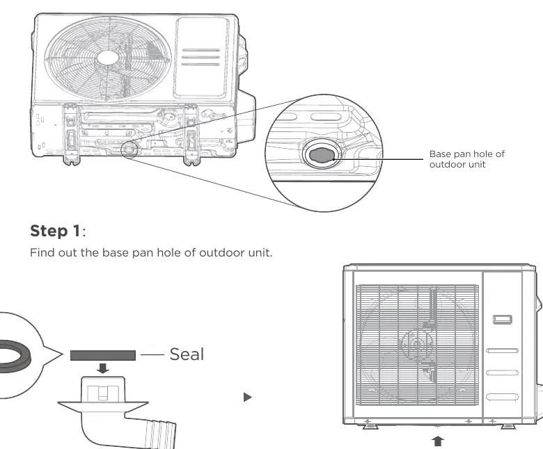
Water leakage from outdoor unit
Ensure the drain fitting is installed correctly and the drain hose is not blocked.
Excessive noise or vibration
Ensure the unit is installed on a firm, level surface and that all mounting bolts are secure.
Before use
- Verify all electrical connections are secure and follow local codes.
- Ensure the unit is installed on a firm, level surface.
- Check that refrigerant piping is properly insulated and connected.
- Confirm the drain hose is installed and clear.
- Perform a vacuum evacuation of the refrigerant circuit.
Specs in practice
- Flare dimension
- The required size of the flared end of the copper pipe to ensure an airtight seal.
Images and diagrams
- Wiring diagrams show connections for various thermostat configurations (2H/2C, 3H/2C, etc.).
- Piping diagrams illustrate the correct flare connection and oil trap installation.
Model compatibility
- Compatible with various ACiQ indoor units.
- Requires specific wiring methods based on the thermostat type (24V vs. communicating).

Manual page author
Emily Carter
User documentation editor
Prepares concise manual descriptions and highlights the most useful setup, operation, and maintenance information for readers.