HVAC / Air Handlers
Installation Manual for ACiQ Wall-Mounted Air Handler
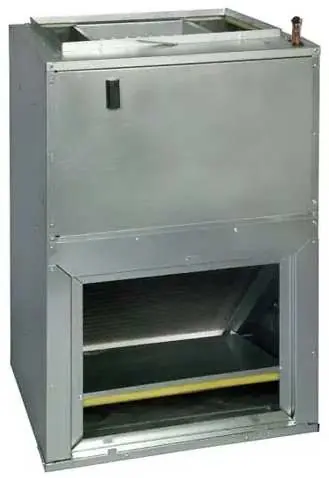
Comprehensive installation guide for ACiQ wall-mounted air handlers. Includes mounting instructions, wiring diagrams, ductwork setup, air evacuation procedures, and technical specifications for models ACiQ-18W-WM through ACiQ-36W-WM.
Quick answers from the manual
Quick answer
- This manual provides installation instructions for ACiQ wall-mounted air handlers, including mounting, wiring, ductwork, and air evacuation procedures. p. 1, 7, 14, 27
Key actions
- Mounting the unit p. 12, 14
- Wiring the unit p. 27, 30
- Evacuating the system p. 38
First start
- Perform a test run after installation to check for leaks, proper drainage, and correct operation. p. 39
Problems and fixes
Unit malfunctions or does not operate as expected
Refer to the Troubleshooting section of the Service Manual before calling customer service.
p. 39Technical specifications
| Parameter | Value | Meaning | Pages |
|---|---|---|---|
| Static Pressure | 0-0.80 in-H2O (0-200 Pa) | Allowed static pressure range. | p. 7 |
Where to find it in the PDF
- Installation p. 7, 14
- Air Evacuation p. 38
Table of contents
Manual images
Click an image to enlargeQuick guide from the manual
This manual provides essential installation and setup instructions for the ACiQ wall-mounted air handler series. Before beginning, ensure the installation location can support the unit's weight (minimum 165 lbs for wall/frame mount) and that all electrical work complies with local and national codes. The unit must be properly grounded and installed by a certified technician.
Indoor unit installation
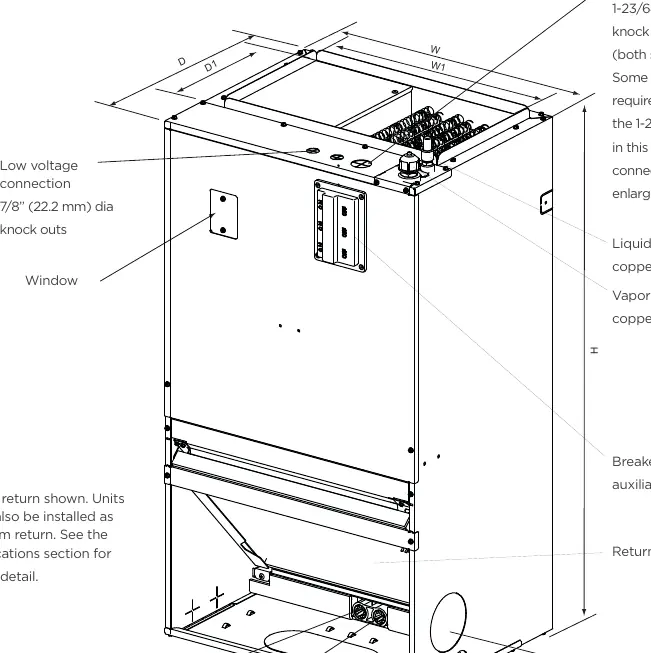
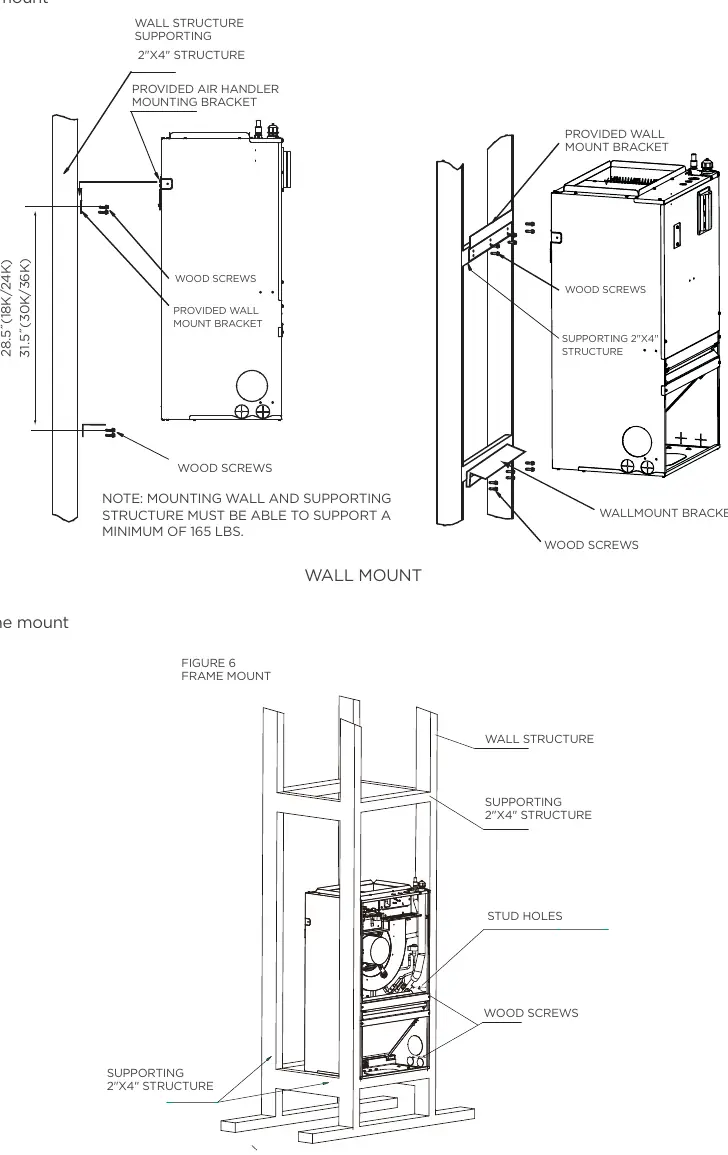
The air handler can be installed using wall mount or frame mount options. The unit must be level from side to side and front to back to ensure proper condensate drainage. Avoid installing in locations with high moisture, flammable gas leaks, or where the air inlet/outlet may be obstructed.
Mounting
- Wall Mount: Use the provided wall mount bracket and wood screws to secure the unit to a supporting structure.
- Frame Mount: Follow the specific frame mount diagram to secure the unit to a supporting 2x4 structure.
Ductwork
The first 36 inches of supply air plenum and ductwork must be constructed of sheet metal as required by NFPA 90B. Ensure the duct system is properly insulated and uses a vapor barrier if running through unconditioned spaces. Do not double filter the return air duct system or filter the supply air duct system.
Wiring
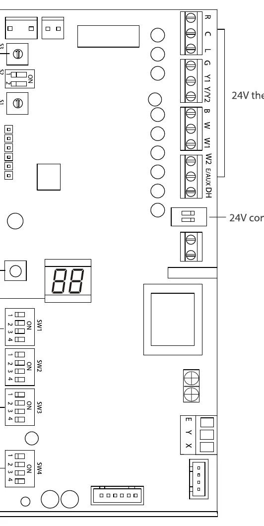
All electrical connections must be made according to the wiring diagram located on the panels of the indoor and outdoor units. Ensure the power supply is properly grounded. The unit supports various thermostat configurations, including 24V thermostats. Use the DIP switch settings on the control board to configure the unit for the specific control scenario (e.g., Free match, Wired controller, 24V Thermostat).
Air evacuation
Evacuation is required upon initial installation and when the unit is relocated. Use a vacuum pump and manifold gauge to remove non-condensable gas and moisture from the refrigerant circuit. Run the vacuum for at least 15 minutes or until the compound meter reads -750 Microns (-10^5 Pa).
Test run
After installation, perform a test run to confirm:
- Indoor and outdoor units are properly installed.
- Piping and wiring are correctly connected.
- The refrigeration system does not leak.
- The drainage system is unimpeded.
- The unit operates without abnormal noise or vibration.
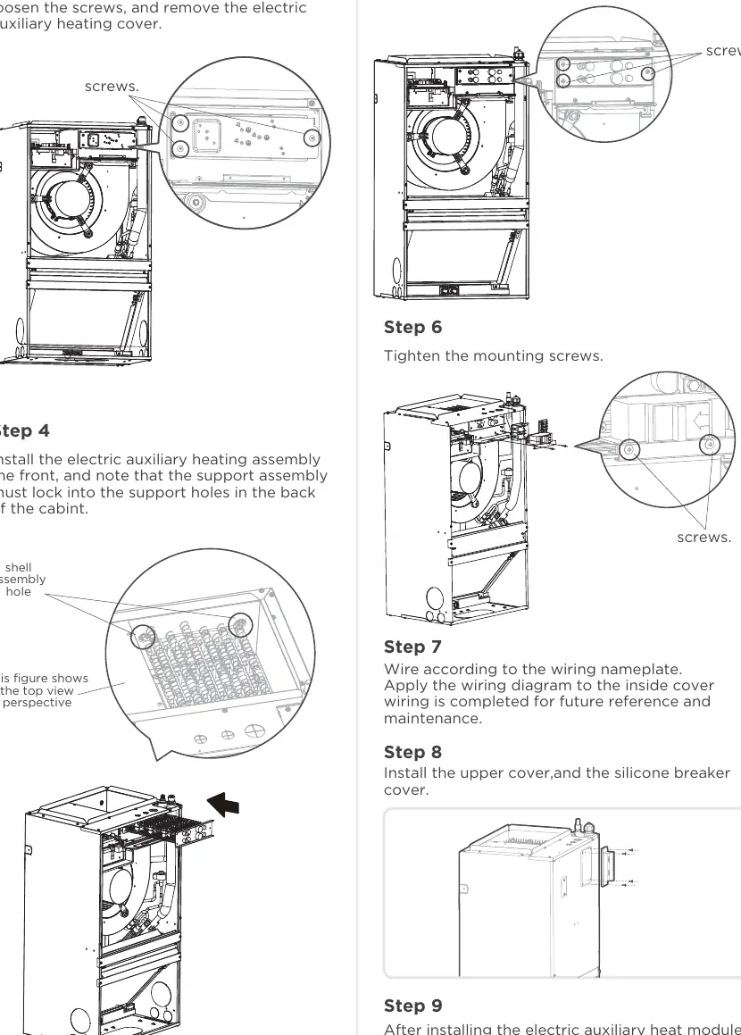
Auxiliary heat module
Optional Electric Auxiliary Heat Modules (3kW to 10kW) can be installed for supplemental heating. Installation must be performed by a licensed contractor. Ensure only matched modules certified for the specific model are used.
Manufacturer information
ACiQ
Practical help
Common problems
Unit not draining properly
Ensure the unit is level from side to side and front to back. Check that the drain pipe is installed correctly and not obstructed.
Condensate leakage
Install a secondary drain pan if the unit is above a finished living space. Ensure proper drainage piping installation.
Airflow issues
Check that the return air duct system has only one filter location. Do not double filter the return air duct system or filter the supply air duct system.
Before use
- Verify the installation location can support the unit's weight (min 165 lbs for wall/frame mount).
- Ensure the unit is level.
- Check that all wiring complies with local and national electrical codes.
- Confirm the power supply is properly grounded.
- Ensure the EPE cushion in the wind turbine is removed.
Specs in practice
- Static Pressure
- The allowed static pressure range is 0-0.80 in-H2O (0-200 Pa).
- Weight Capacity
- Mounting structures must support a minimum of 165 lbs (wall mount) or 360 lbs (general location).
Images and diagrams
- Wiring diagrams are provided for various thermostat configurations (4H/2C, 3H/2C, etc.).
- DIP switch settings determine control scenarios (Free match, Wired controller, 24V Thermostat).
Model compatibility
- Compatible with 24V thermostats.
- Optional Electric Auxiliary Heat Module available in 3kW to 10kW sizes.

Manual page author
Michael Turner
Technical manual editor
Reviews PDF manuals for structure, safety notes, and practical product details so readers can find the right information quickly.