Lighting / Fixtures
Installation Manual for Acroma 2333BGCR Semi-Flush Mount Light
A comprehensive installation guide for the Acroma 2333BGCR 3-Light Semi-Flush Mount Light. This manual includes essential safety warnings, a list of required tools, hardware identification, step-by-step assembly instructions, and a...
Quick answers from the manual
Quick answer
- The Acroma 2333BGCR is a 3-light semi-flush mount fixture. Installation involves mounting the crossbar to the junction box, connecting the supply wires to the fixture wires, securing the canopy, and attaching the glass shades. p. 1, 2, 3
Key actions
- Turn off power at the circuit breaker. p. 1
- Connect wires: White to White, Black to Black, Ground to Ground. p. 3
Technical specifications
| Parameter | Value | Meaning | Pages |
|---|---|---|---|
| Bulb Type | 3 x Max 60W | Maximum wattage per bulb | p. 1 |
Show 1 more answers Show less
Where to find it in the PDF
- Safety and Tools p. 1
- Hardware and Assembly Overview p. 2
- Installation Steps and Wiring p. 3
Table of contents
Manual images
Click an image to enlargeQuick guide from the manual
This document provides instructions for the safe installation of the Acroma 2333BGCR 3-Light Semi-Flush Mount Light. Before beginning, ensure the power is turned off at the circuit breaker. The installation requires basic electrical knowledge; if you are unsure, consult a qualified electrician.
Safety Information
- Turn off power: Always disconnect power at the circuit breaker or fuse box before starting installation.
- Voltage testing: Use a voltage tester to ensure wires are not live before touching them.
- Tools: Use tools with insulated handles and ladders made of wood or fiberglass.
- Protection: Keep children away and cover unused outlets.
Tools Required
The following tools are required for installation (not included):
- Phillips screwdriver
- Wire stripper
- Pliers
- Safety goggles
- Electrical tape
Hardware Included
Ensure all parts are present before starting:

- Canopy (A)
- Crossbar assembly (B)
- Outlet box screws (short) (C)
- Green ground screw (D)
- Wire connectors (E)
- Finials (F)
- Support screws (long) (G)
- Hex nuts (H)
- Flat washers (I)
- Glass shades (J)
- Socket rings (K)
Assembly and Installation
- Preparation: Determine the required length of the stem or chain.
- Mounting: Attach the mounting plate (crossbar assembly) to the junction box.
- Wiring: Connect the fixture wires to the supply wires using the provided wire connectors. Ensure proper grounding.
- Hanging: Secure the fixture to the ceiling using the canopy and support screws.
- Finishing: Install the glass shades and secure them with the socket rings.
Wiring Instructions
Follow these standard wiring connections:
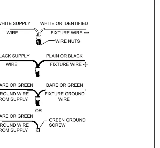
- White Supply Wire: Connect to the White or Identified Fixture Wire.
- Black Supply Wire: Connect to the Plain or Black Fixture Wire.
- Ground Wire: Connect the Bare or Green Ground Wire from the supply to the Fixture Ground Wire or the Green Ground Screw on the mounting plate.
Practical help
Common problems
Fixture does not light up
Check if the power is on at the circuit breaker and verify all wire connections are secure.
Unsure about electrical wiring
Consult a qualified electrician if you have any electrical questions or if new wiring is required.
Before use
- Turn off the main power supply at the circuit breaker.
- Verify all tools (Phillips screwdriver, wire stripper, pliers, etc.) are available.
- Check that all hardware components listed are included.
- Ensure the mounting surface is stable.
- Use a voltage tester to confirm the circuit is not live.
Show more Show less
Specs in practice
- Bulb Requirement
- The fixture uses 3 bulbs with a maximum of 60W each, Medium Base.
Images and diagrams
- The wiring diagram illustrates connecting white-to-white, black-to-black, and ground-to-ground wires using wire nuts.
- Assembly steps show the sequence of attaching the canopy, mounting plate, and securing the glass shades.
Model compatibility
- Designed for standard residential electrical junction boxes.
- Not suitable for outdoor use unless specified.

Manual page author
Michael Turner
Technical manual editor