Lighting / Fixtures
Installation Instructions for American Lighting Association LED Bath Vanity Light 2413-695-L / 2414-695-L
A comprehensive installation guide for American Lighting Association LED Bath Vanity Light models 2413-695-L and 2414-695-L. Includes step-by-step wiring, mounting, and safety instructions.
Quick answers from the manual
Quick answer
- This document provides installation instructions for American Lighting Association LED Bath Vanity Light models 2413-695-L and 2414-695-L, covering mounting, wiring, and glass attachment. p. 1
Key actions
- Shut off power at the fuse or circuit breaker box before starting installation. p. 1
Technical specifications
| Parameter | Value | Meaning | Pages |
|---|---|---|---|
| Dimming | ELV / LED compatible | Compatible with ELV and/or LED wall dimmer switches | p. 1 |
Show 1 more answers Show less
Where to find it in the PDF
- Installation Instructions p. 1
Table of contents
Manual images
Click an image to enlargeImportant Safety Information
Before beginning the installation, you must shut off the power at the fuse box or circuit breaker box. Failure to do so may result in electrical shock or injury.
Preparation
Carefully unpack your new fixture and lay out all parts in a clean area to ensure nothing is missing. You will need to remove the old fixture and its mounting hardware before proceeding.
Installation Steps
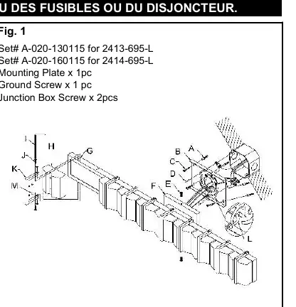
- Mounting Plate: Loosen the mounting screw (E) to remove the mounting plate (B) from the backplate (F). Position the mounting plate (B) on the wall and mark the location for the four mounting holes. Pre-drill the holes, insert the plastic anchors (A), and secure the plate to the junction box using the provided screws (D). Ensure the side marked “GND” faces out.
- Support Cable: Attach the hook of the support cable (L) into the slot on the mounting plate (B) to support the weight of the fixture while you perform the wiring.
- Wiring: Connect the electrical wires as shown in the wiring diagram. If your junction box has a ground wire (green or bare copper), connect the fixture's ground wire to it. Otherwise, connect the fixture's ground wire directly to the mounting plate (B) using the provided green screw.
- Final Assembly: Tuck the wire connectors neatly into the junction box. Raise the backplate (F), align it with the holes on the mounting plate (B), and secure it with the mounting screws (E).
- Glass Attachment: Attach the bracket (K) to the glass (H), hang the bracket (K) on the metal square box (G), and secure it using the provided Allen screws (J) and Allen wrench (I). If necessary, use the plastic washer (M) to adjust the glass position.
Wiring Guide
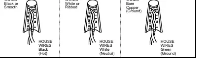
- Black (Hot) Wire: Connect to the black or smooth fixture wire.
- White (Neutral) Wire: Connect to the white or ribbed fixture wire.
- Green (Ground) Wire: Connect to the bare copper fixture wire.
Technical Specifications
This fixture is dimmable with ELV and/or LED compatible wall dimmer switches.
Practical help
Common problems
Fixture not dimming correctly
Ensure you are using an ELV or LED compatible wall dimmer switch.
Glass is misaligned
Use the provided plastic washer (M) to adjust the position of the glass.
Before use
- Shut off power at the fuse or circuit breaker box
- Ensure you have the mounting plate, ground screw, and junction box screws
- Verify compatibility with your wall dimmer switch
- Ensure the junction box is installed and ready
Show more Show less
Images and diagrams
- Fig. 1 illustrates the mounting plate installation and the use of the support cable.
- Fig. 2 provides a clear guide for connecting the Hot, Neutral, and Ground wires.
Model compatibility
- Compatible with ELV and/or LED wall dimmer switches.

Manual page author
David Miller
Documentation analyst