Lighting / Fixtures
Installation and Maintenance Manual for Acuity Brands 247L Series LED Post-top Lantern
Comprehensive installation and maintenance guide for the Acuity Brands 247L Series LED post-top lantern. Includes step-by-step mounting instructions, wiring procedures, photocontrol setup, and field adjustable output (AO) module settings.
Quick answers from the manual
Quick answer
- The 247L Series is an outdoor LED post-top lantern. Installation involves mounting on a 2.375"-3" pole, wiring to the internal terminal block (35 in-lbs torque), and optional configuration of the photocontrol and Field Adjustable Output (AO) module. p. 3, 4, 5
Key actions
- Mounting the fixture p. 3
- Wiring the fixture p. 4
- Adjusting AO Module p. 5
Problems and fixes
Photocontrol orientation
Rotate cupola base until window faces North.
p. 4Show 3 more answers Show less
Maintenance and reset
- Cleaning the refractor/lens p. 1
Technical specifications
| Parameter | Value | Meaning | Pages |
|---|---|---|---|
| Pole Diameter | 2.375" - 3" | Acceptable pole top exterior diameter | p. 3 |
| Closure Screw Torque | 25-35 in-lbs | Required torque for closing the hood | p. 3 |
| Terminal Block Torque | 35 in-lbs | Required torque for terminal block screws | p. 4 |
Where to find it in the PDF
- Safety Instructions p. 1, 2
- Mounting and Opening p. 3
- Wiring and Ladder Rest p. 4
- Field Adjustable Output p. 5
Table of contents
Manual images
Click an image to enlargeImportant Safety Information
Before installing or servicing the luminaire, read all warnings. Installation and service must be performed by a qualified licensed electrician. Ensure the power is disconnected before starting. The fixture must be grounded to reduce the risk of electric shock. Wear gloves and safety glasses during installation and maintenance. Do not operate in close proximity to combustible materials.
Mounting Instructions
The unit is designed for pole tops with an exterior diameter between 2.375" and 3".
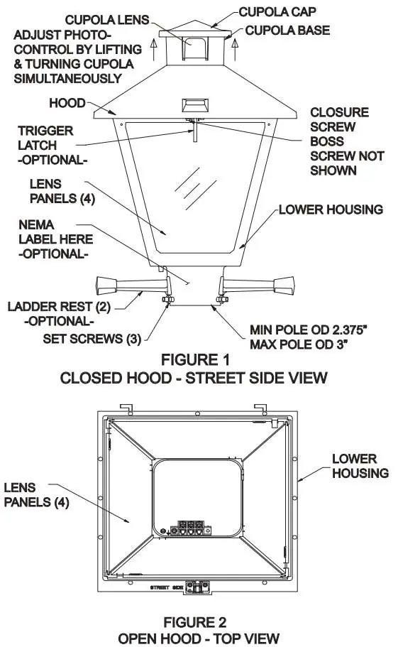

- Feed the supply leads through the base of the unit when placing it on the pole.
- Orient the unit so that the closure screw (or optional trigger latch) faces the street side.
- Tighten the three mounting set screws.
Opening and Closing the Unit
To open the fixture, locate the closure screw on the street side. Unscrew the captive closure screw until it moves freely, then open the hood. To close, shut the hood and re-tighten the captive closure screw to 25-35 in-lbs of torque. If equipped with an optional trigger latch, pull the trigger while pushing up on the hood to open; press down to engage the latch when closing.
Wiring
- Open the unit and remove the street side lens.
- Unscrew the captive thumb screw on the bottom cover and remove the cover if applicable.
- Locate the wiring diagram inside the hood.
- Connect power supply leads to the terminal block. The recommended torque for terminal block screws is 35 in-lbs.
- Push down the terminal block cover, replace the bottom cover, and reinstall the lens.
Ladder Rest Installation
The ladder rest is a press-fit design intended for installation after the unit is mounted.
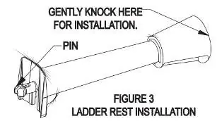
- Insert the pin feature into the ladder rest hole located on the left and right side of the lower housing.
- Using a rubber mallet or hammer, gently knock the ladder rest into the hole, ensuring it remains aligned.
Note: The ladder rest is designed to break away under side force. If the pin is damaged, it can be reattached using a 1/4-20x3/4 bolt and nut.
Photocontrol Installation
No tooling is required for photocontrol installation.
- Remove the cupola cap by lifting it off.
- Insert the photocontrol into the receptacle.
- Reattach the cupola cap until it snaps into place.
- Turn the photocontrol window toward the North by grabbing the cupola base and rotating it.
Field Adjustable Output (AO) Module
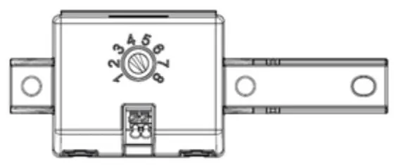
The AO module allows adjustment of light output and input wattage to meet site-specific requirements. The module features a dial with positions 1 through 8, where 8 provides 100% output and 1 provides 20% output.
Practical help
Common problems
Photocontrol not working or facing wrong direction
Rotate the cupola base until the photocontrol window faces North. Ensure the photocontrol is fully seated in the receptacle.
Ladder rest pin damaged
Remove the damaged pin with pliers and reattach the ladder rest using a 1/4-20x3/4 bolt and nut.
Closure screw difficult to engage
Ensure the hood is fully closed and aligned before tightening the captive closure screw to 25-35 in-lbs.
Before use
- Verify supply voltage matches luminaire label
- Ensure pole diameter is between 2.375" and 3"
- Disconnect power before installation
- Wear gloves and safety glasses
- Ensure proper grounding of the fixture
Show more Show less
Specs in practice
- Pole Diameter
- Accepts pole tops with exterior diameter between 2.375" and 3"
- Closure Screw Torque
- Tighten to 25-35 in-lbs
- Terminal Block Torque
- Tighten to 35 in-lbs
Images and diagrams
- Figure 1: Closed hood view showing closure screw and pole mounting requirements
- Figure 2: Open hood view showing internal components and terminal block location
- Figure 3: Ladder rest installation showing pin insertion and alignment
Model compatibility
- Compatible with pole tops 2.375" to 3" in diameter
- AO module available on MVOLT options
- Not for use near maritime safety communications equipment operating between 0.45-30 MHz

Manual page author
David Miller
Documentation analyst