Lighting / Fixtures
Installation Guide for CPX LED Flat Panel Light Fixture
Comprehensive installation and wiring guide for the CPX LED Flat Panel Light Fixture. Includes safety warnings, mounting instructions for T-Grid and suspension, wiring diagrams, and control configuration for ALO SWW, nLight, and other...
Quick answers from the manual
Quick answer
- This document provides installation, wiring, and configuration instructions for the CPX LED Flat Panel Light Fixture, including mounting options and control settings. p. 1, 3, 4, 6
Key actions
- Mounting to T-Grid p. 6
- Wiring the fixture p. 4
First start
- Ensure power is off, make electrical connections according to local codes, and set ALO SWW switches before closing the ceiling. p. 4, 7
Show 4 more answers Show less
Problems and fixes
Battery failure
Check LED status codes; flashing red (once per 6 sec.) indicates battery failure.
p. 8Maintenance and reset
- Use button sequences on the test switch to initiate manual tests (e.g., 2 X Press and Release for 60-Second Test). p. 8
Technical specifications
| Parameter | Value | Meaning | Pages |
|---|---|---|---|
| Dimming | 0-10V | Low voltage dimming control | p. 4, 7 |
Where to find it in the PDF
- Installation Instructions p. 1, 3, 4, 5
- Controls and Options p. 7, 8
Table of contents
Manual images
Click an image to enlargeImportant Safety Information
Before installing, servicing, or performing routine maintenance, read all warnings and instructions. Installation and service should be performed by a qualified licensed electrician. Always disconnect power before installation. Wear gloves and safety glasses at all times. Ensure proper grounding to prevent fixture failure.
Product Overview
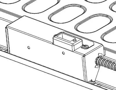
The CPX LED Flat Panel Light Fixture is designed for T-Grid ceiling installation. Key components include the main driver enclosure, and optional modules such as emergency battery, occupancy sensors, and control enclosures.
Installation
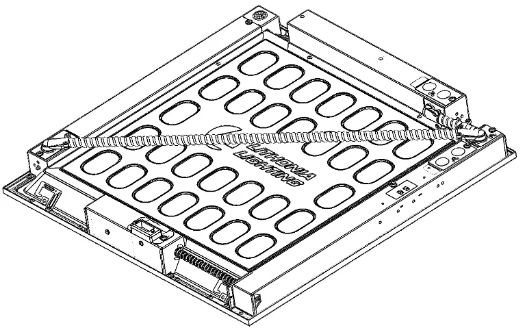
Mounting
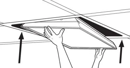
T-Grid Mounting: Place the fixture in the appropriate T-Grid ceiling structure. From above the ceiling, bend the attached T-Grid clips over the T-Grid on all 4 corners to secure the fixture.
Suspension Mounting: Use the hanger wire holes at all 4 corners and appropriately rated hanging cables (not included) to suspend the fixture.
LATC Option: If using the LATC accessory, remove the standard T-Grid clips using hand tools only (no power tools). Replace them with the LATC adapter and secure using the provided screws.
Wiring
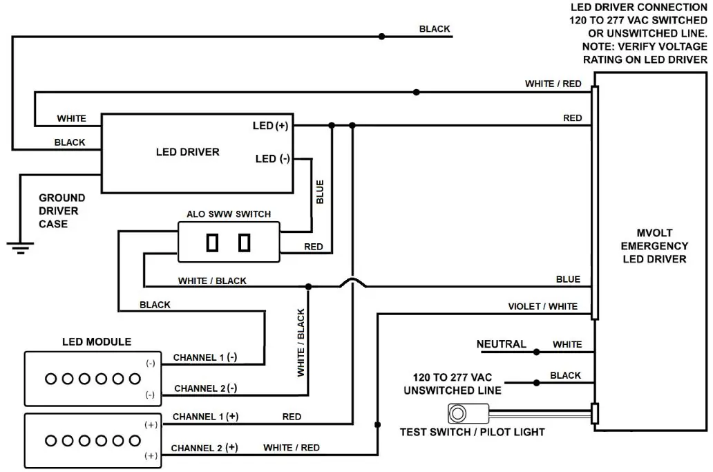
Remove the access plate to reach the fixture wires. Make electrical connections according to local codes:
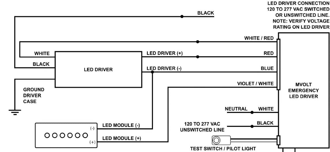
- Green: Ground
- White: Neutral line in
- Black: Hot line in
If dimming leads (purple and pink) are not used, cap them off. Reinstall the access plate after wiring is complete.
Controls and Options
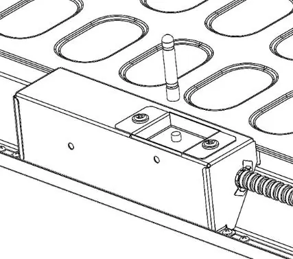
ALO SWW (Adjustable Lumen, Switchable White)
Two switches on the back of the Main Driver Enclosure allow for adjustment of light output (low, medium, high) and color temperature (3500K, 4000K, 5000K). These must be set before installation as they are not accessible once the fixture is mounted.
Other Controls
- 0-10V Dimming: Standard low-voltage dimming.
- SLD (Step Level Dimming): Uses two switched circuits to achieve 100% or 50% light output.
- nLight/Wireless Controls: Requires specific connection points (CAT5e or antenna assembly) as detailed in the manual.
Troubleshooting and Maintenance
If the fixture includes an emergency battery, use the test switch to perform manual tests. LED status codes indicate battery health (e.g., flashing green for testing, flashing red for failure). Clean the outside of the refractor/lens with warm water and mild, non-abrasive detergent as needed.
Practical help
Common problems
Fixture not dimming correctly
Ensure 0-10V dimming leads are connected properly and not capped off if in use.
Wireless communication not working (NLTAIR2)
Ensure the external antenna is threaded onto the post on the controls enclosure. Do not use power tools.
Emergency battery not working
Ensure the test switch is installed and the battery is charged; note that emergency mode overrides dimming/color controls.
Before use
- Verify supply voltage matches luminaire label
- Ensure power is OFF before installation
- Use appropriate mounting hardware for the ceiling structure
- Wear safety glasses and protective gloves
- Set ALO SWW switches before closing the ceiling
Show more Show less
Specs in practice
- 0-10V Dimming
- Standard low-voltage dimming control interface.
Images and diagrams
- Wiring diagrams for standard, battery, and GTD configurations
- T-Grid and suspension mounting steps
- ALO SWW switch settings
Model compatibility
- Compatible with standard T-Grid ceiling structures
- Emergency battery only energizes higher color LEDs in emergency mode
- 0-10V dimming leads are for low voltage dimming only

Manual page author
Emily Carter
User documentation editor