Lighting / Fixtures
Installation Instructions for Juno 15IN FMLSQ Series LED Flush Mount Ceiling Light
A comprehensive installation and operation guide for the Juno 15IN FMLSQ Series LED flush mount ceiling light. Includes steps for mounting, wiring, color temperature adjustment, and troubleshooting.
Table of contents
Manual images
Click an image to enlargeQuick Guide
This document provides installation and operation instructions for the Juno 15IN FMLSQ Series LED flush mount ceiling light. Key features include switchable color temperatures (2700K to 5000K), a night light mode, and compatibility with standard residential dimmers. Ensure power is turned off at the circuit breaker before beginning any installation or maintenance.
Product Overview
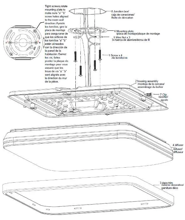
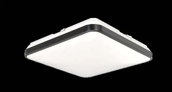
The Juno FMLSQ series is a low-profile, square LED fixture designed for surface mounting on new or existing junction boxes. The package includes the LED fixture, mounting plate, wire nuts, screws, and an optional black trim ring.
Installation Preparation
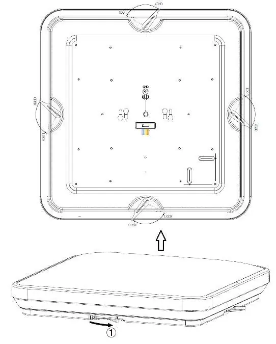
Before installing, ensure the electrical power to the junction box is turned off. Remove the fixture components from the carton and verify all parts are present. To prepare the fixture for installation, place it on a flat surface and remove the diffuser by rotating the four clips to the OPEN position, then lift the diffuser from the housing assembly.
Trim Ring Replacement
The fixture comes with a white trim ring by default. To change to the included black trim ring: remove the white ring from the diffuser by gently lifting from one corner at the bottom edge. Install the black trim ring by starting at one corner and snapping the remaining corners into place to secure it to the diffuser.
Color Temperature Adjustment
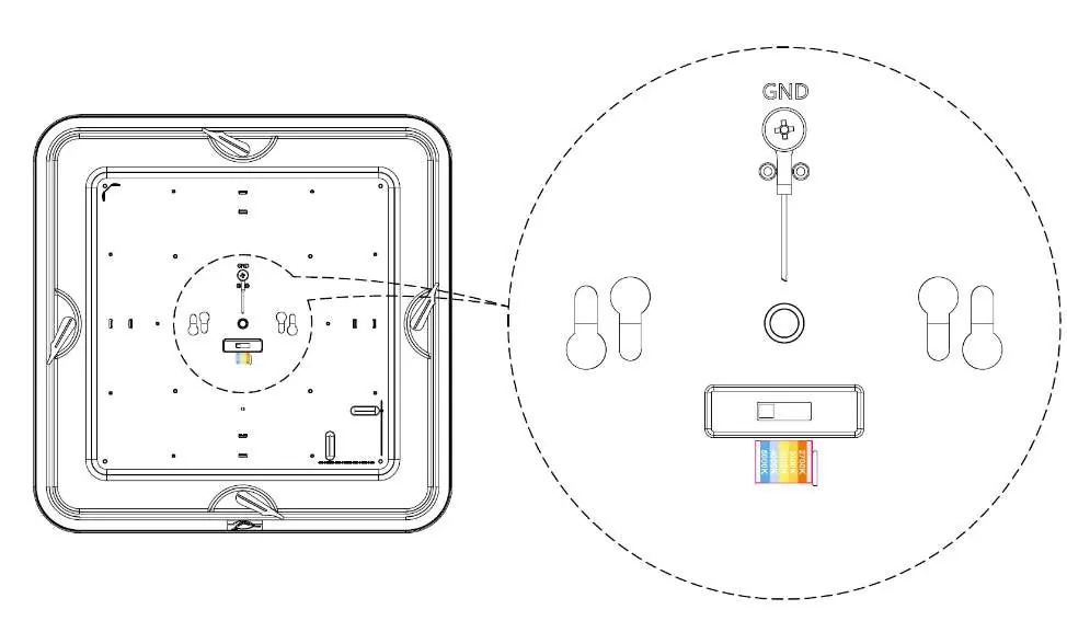
The fixture features a switchable color temperature (CCT) setting. Locate the switch on the LED module and select your desired color temperature: 2700K (soft), 3000K (warm), 3500K (neutral), 4000K (cool), or 5000K (day light).
Electrical Connection
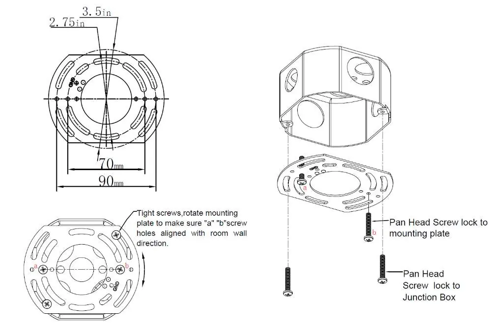
Install two screws into the junction box, leaving the screw heads approximately 1/4 inch from the mounting plate. Rotate the mounting plate to align with the room wall direction and secure it. With power off, connect the fixture's copper ground wire to the junction box's bare copper wire using a wire nut. Connect the black fixture wire to the black power supply wire and the white fixture wire to the white power supply wire using wire nuts.
Final Assembly
Position the wires into the junction box and slide the housing assembly into the keyhole's lock position. Secure the housing with the two screws using a Phillips screwdriver. Reinstall the diffuser by aligning the edges and rotating the clips into the LOCK position. Turn on the power to verify the installation.
Night Light Mode
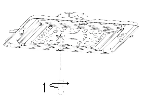
To activate night light mode from normal mode: turn the light switch ON, then OFF, then ON again within 1 second. Repeat this process to return to normal mode.
Troubleshooting
If the fixture fails to operate properly, verify that the line voltage is correct, ensure the fixture is wired correctly, and confirm it is properly grounded. For further assistance, contact product tech support at [email protected].
Practical help
Common problems
Fixture fails to operate
Verify line voltage, ensure proper wiring connections, and confirm the fixture is correctly grounded.
Radio or TV interference
Reorient or relocate the receiving antenna, increase separation between the equipment and receiver, or connect to a different circuit.
Before use
- Turn off electrical power at the circuit breaker or fuse.
- Verify junction box compatibility (see Figure 3 for dimensions).
- Wear safety glasses and gloves.
- Ensure black, white, and copper wires are available.
- Check that all parts are included in the carton.
Show more Show less
Images and diagrams
- Figure 1: Exploded view of the fixture assembly.
- Figure 4: Instructions for removing the diffuser.
- Figure 7: Location of the CCT adjustment switch.
- Figure 9: Wiring connection diagram.
- Figure 14: Visual representation of night light mode.
Model compatibility
- Compatible with several standard residential dimmers; check acuitybrands.com for a recommended list.
- Not intended for use with emergency exits or emergency lighting.

Manual page author
David Miller
Documentation analyst