Lighting / Outdoor Lighting
Installation and Maintenance Manual for Contempo Post Top 245L Series
A comprehensive installation and maintenance guide for the Contempo Post Top 245L Series lighting fixture. Includes detailed mounting procedures, wiring instructions, safety precautions, and field adjustable output settings.
Quick answers from the manual
Quick answer
- The Contempo Post Top 245L Series is an outdoor lighting fixture. Installation requires mounting on a 2.375"-3" pole, wiring to a terminal block (35 in-lbs torque), and securing the hood. It features an optional Field Adjustable Output (AO) module to customize light output. p. 3, 4
Key actions
- Mounting the fixture p. 3
- Wiring the fixture p. 3
- Adjusting output p. 4
Problems and fixes
Interference with other electrical devices
Move the device away from the luminary or plug into a different outlet.
p. 3Show 2 more answers Show less
Technical specifications
| Parameter | Value | Meaning | Pages |
|---|---|---|---|
| Pole Diameter | 2.375" - 3" | Acceptable pole top diameter | p. 3 |
| Terminal Block Torque | 35 in-lbs | Recommended torque for terminal block screws | p. 3 |
| Mounting Set Screw Torque | 15 ft-lb | Maximum torque for mounting set screws | p. 3 |
Where to find it in the PDF
- Safety Instructions p. 1, 2
- Installation and Maintenance p. 3
- Field Adjustable Output Module p. 4
Table of contents
Manual images
Click an image to enlargeImportant Safety Information
Read and follow all safety instructions before installation. Failure to follow these instructions could void product warranties and result in serious injury or death.
- Electrical Safety: Disconnect or turn off power before installation or servicing. Verify that supply voltage is correct by comparing it with the luminaire label. All electrical and grounded connections must be in accordance with the National Electrical Code (NEC) and any applicable local code requirements.
- Handling: Wear gloves and safety glasses at all times when removing the luminaire from the carton, installing, servicing, or performing maintenance.
- Usage: This product is for outdoor installation and use only. Do not operate in close proximity to persons, combustible materials, or substances affected by heat or drying.
- ESD Precautions: LED products are polarity sensitive and susceptible to Electrostatic Discharge (ESD). Wear personal grounding equipment during installation or servicing.
Mounting Instructions
This unit is designed to accept pole tops with an exterior diameter between 2.375" and 3".
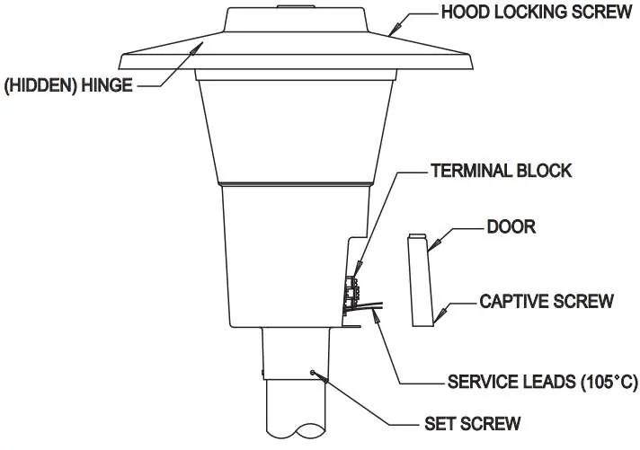

- Remove the access door by loosening the captive screw.
- Pull service leads through the base assembly and out the access door opening.
- Orient the unit so the door is facing the street side.
- Tighten the three mounting set screws. Caution: Do not tighten set screws beyond 15 ft-lb torque.
Wiring
Note: This procedure is not necessary if the unit is supplied with pre-wire.
- Pull up the terminal block cover.
- Connect service leads to the terminal block. Refer to the wiring diagram on the inside of the access door. Recommended torque for terminal block screws is 35 in-lbs.
- Push down the terminal block cover.
- Replace the access door and secure it with the captive screw.
Hood Installation
- Install the hood onto the base assembly by inserting the hinge bar of the base into the hinge bracket on the underside of the hood. Swing the hood over and into place.
- If the unit includes photocontrol, connect the quick connectors before closing the hood.
- Fasten the hood locking screw.
Photocontrol
No tooling is necessary for photocontrol installation or adjustment.
- Lift and rotate the receptacle so that the arrow on the top points north. Release the receptacle.
- Plug the photocontrol into the receptacle and twist it clockwise until it locks into position.
Field Adjustable Output Module
The Field Adjustable Output (AO) module is an onboard device that adjusts light output and input wattage to meet site-specific requirements. The AO option is available on the 245L series.
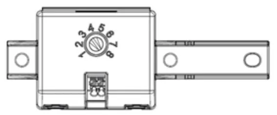
- Adjustment: The module features a dial with positions 1 through 8.
- Performance: Adjusting the position changes the percentage of lumens and wattage output (e.g., Position 8 provides 100% output, while Position 1 provides 20% output).
Maintenance
Clean the fixture with mild soap or household-type detergent. Do not use acid or caustic cleaners.
Practical help
Common problems
Radio or TV interference
Move the device away from the luminary or plug it into a different outlet.
Before use
- Verify supply voltage matches luminaire label
- Ensure pole top diameter is between 2.375" and 3"
- Wear gloves and safety glasses
- Disconnect power before installation
- Ensure electrical distribution system meets NEC requirements
Show more Show less
Specs in practice
- Terminal Block Screw Torque
- 35 in-lbs
- Mounting Set Screw Torque
- Do not exceed 15 ft-lbs
- Pole Diameter Compatibility
- 2.375" to 3"
Images and diagrams
- The diagram illustrates the assembly components, including the hood locking screw, terminal block, access door, and set screws.
Model compatibility
- Compatible with pole tops between 2.375" and 3" diameter.
- AO module data provided is for MVOLT options only.

Manual page author
Emily Carter
User documentation editor