Electronics / Amplifiers Receivers
User Manual for Adastra RS Series Rackmount 100V Slave Amplifiers
Quick guide for Adastra RS Series rackmount 100V slave amplifiers. Learn about installation, wiring 100V or 8Ω systems, operation, and troubleshooting for models RS120, RS240, RS360, and RS480.
Table of contents
Manual images
Click an image to enlargeQuick Guide from the Manual
The Adastra RS Series are rackmount 100V slave amplifiers designed for public address systems. They are intended to be fed from a mixer or mixer-amplifier signal output. Key safety requirements include ensuring correct mains voltage, using double-insulated speaker wire for 100V systems, and never connecting 8Ω and 100V terminals simultaneously. Ensure adequate ventilation and support when rack-mounting.
Front Panel Controls
The front panel features simple controls for operation:
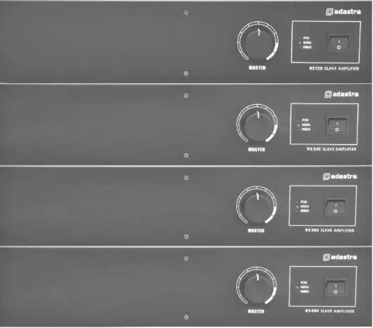
- MASTER volume control: Adjusts the output level.
- LED indicators: Includes POWER, SIGNAL, and PEAK indicators.
- Power switch: Turns the unit on or off.
Rear Panel Connections
The rear panel contains all necessary inputs and outputs:
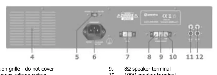
- Power: IEC mains inlet with fuse holder and voltage selector. RS120 and RS240 models also feature 24Vdc screw terminals for battery power.
- Speaker Outputs: Includes 8Ω terminal, 100V terminal, and COM (common) terminal.
- Signal: SLAVE IN (dual RCA) for receiving audio and SLAVE OUT (RCA) for daisy-chaining additional amplifiers.
Installation and Wiring
The amplifier can be configured for 100V line systems or low impedance systems. These configurations cannot be used together.
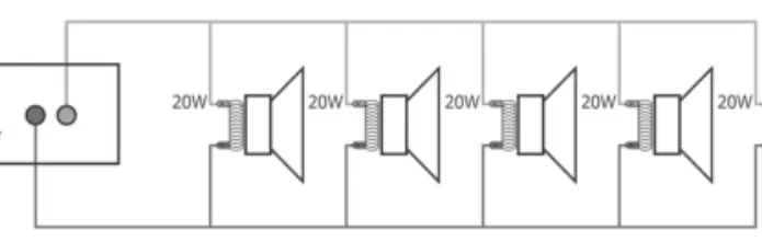
100V Line Systems
Connect the 100V output terminal to the positive (+) connection of the speaker and the COM output to the negative (-) connection. Connect further speakers in parallel. Ensure the combined wattage of all speakers does not exceed 90% of the amplifier's output power rating.
Low Impedance Systems
Connect the 8Ω output terminal to the positive (+) speaker connection and the COM output to the negative (-) connection. Ensure the speaker load is no less than 8Ω and the speaker's power handling is equal to or greater than the amplifier's output.
Operation
Turn the MASTER volume control fully down before switching on the power. Once powered, ensure the signal is active on the SLAVE IN inputs and gradually turn up the MASTER volume. The PEAK LED should only light momentarily; if it stays lit, reduce the volume to avoid distortion or clipping.
Troubleshooting
If you encounter issues, check the following:
- No power LED: Check the IEC lead, mains fuse, or battery charge (if using 24Vdc).
- Power LED on but no output: Check input signal connections and ensure the MASTER volume is turned up.
- Distorted output: Reduce the MASTER volume level; the input signal may be too high.
- Amplifier overheating: Ensure cooling vents are clear, verify that 8Ω and 100V speakers are not mixed, and check that the total load on the 8Ω output is not less than 8Ω.
Specifications
The RS Series includes four models: RS120, RS240, RS360, and RS480. All models feature 110/230Vac power supply. RS120 and RS240 support 24Vdc power. Output power ranges from 120Wrms to 480Wrms depending on the model. All units feature Master volume control and <1.0% THD.
Practical help
Common problems
No power LED on control panel
Ensure IEC lead is connected properly, check mains inlet fuse, or if using 24Vdc, ensure the battery is charged.
Power LED is on but no output
Check input signal leads and ensure the MASTER volume control is turned up.
Output is very loud or distorted
Reduce the MASTER volume level and check if the input signal level is too high.
Amplifier overheating
Ensure cooling vents are clear, verify 8Ω and 100V speakers are not connected simultaneously, and ensure 8Ω load is not less than 8Ω.
Before use
- Ensure mains voltage matches the setting on the voltage selector.
- Use double-insulated speaker wire for 100V connections.
- Do not connect 8Ω and 100V terminals at the same time.
- Ensure adequate air-flow around the unit.
- For rack-mounting, ensure the rack supports the weight of the amplifier.
Specs in practice
- SLAVE IN/OUT
- RCA connections for receiving audio signal and daisy-chaining to additional amplifiers.
Images and diagrams
- 100V Wiring: Connect the 100V terminal to the positive (+) speaker wire and the COM terminal to the negative (-) speaker wire.
Model compatibility
- RS120 and RS240 models support 24Vdc battery power.
- RS360 and RS480 models do not support 24Vdc power.

Manual page author
Emily Carter
User documentation editor
Prepares concise manual descriptions and highlights the most useful setup, operation, and maintenance information for readers.