Electronics / Amplifiers Receivers
Adastra RMC Series Rackmount 100V Mixer Amplifier User Manual
Quick guide for the Adastra RMC Series rackmount 100V mixer amplifier with CD player. Learn about connections, DIP switch settings, speaker wiring, and operating the built-in audio player.
Table of contents
Manual images
Click an image to enlargeQuick guide from the manual
The Adastra RMC-series is a rackmount 100V mixer-amplifier with an integrated CD, Bluetooth, DAB+/FM, USB, and SD player. This unit is designed for public address systems. Important: Always ensure the amplifier is switched off before making any connections or changing DIP switch settings to prevent damage to the system or speakers.
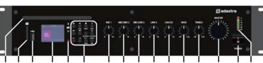
Front and rear panel controls
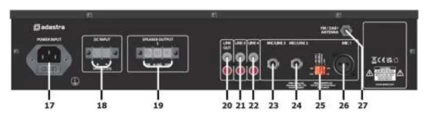
The front panel features controls for CD/SD/USB playback, microphone and line input volumes, bass and treble EQ, and the master volume. The rear panel contains the mains IEC inlet, DC power terminals (for 24V battery operation), speaker output terminals, line inputs (RCA and jack), and the FM antenna connection.
Connection and setup
Mains and DC Power: Connect the supplied mains lead to the IEC inlet. Alternatively, the unit can be powered by a 24V battery (e.g., lorry or boat battery) via the DC terminals. Ensure DC cables are capable of handling at least 10A.
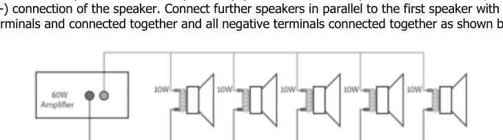
Speaker Connections: The RMC series can be used as a 100V line amplifier or a standard low-impedance amplifier. Do not use both configurations simultaneously. For 100V systems, connect the positive (+) speaker wire to the 100V terminal and the negative (-) to the COM terminal. For low-impedance systems (4-16Ω), connect to the 4-16Ω and COM terminals.
DIP switch configuration
The DIP switches on the rear panel allow for specific channel configurations. Note: Change these settings only when the amplifier is powered off.
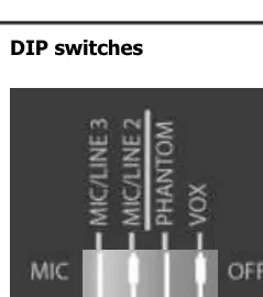
- Phantom Power: Provides +20V to the MIC 1 input for condenser microphones.
- VOX Control: Automatically attenuates line inputs 4 and 5 by -40dB when a signal is detected on MIC 1.
- Sensitivity: MIC/LINE 2 and 3 inputs can be toggled between MIC and LINE sensitivity to match the input source.
Operation and audio player
Basic Operation: Turn all volume controls down before powering on. Set EQ controls to the 12 o'clock position. Gradually increase the master volume and individual channel volumes. The level meter LEDs indicate output; ensure the red '0' LED only lights momentarily.
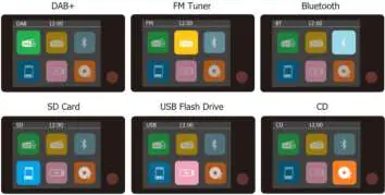
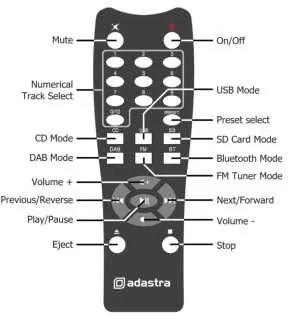
Audio Player: Use the source select button to toggle between DAB+, FM, Bluetooth, SD, USB, and CD modes. The built-in player supports MP3 files on USB/SD media (formatted to FAT32, 32GB max). Bluetooth pairing is initiated via the SOURCE/PAIR button; search for 'Adastra RMC***D' on your device.
Troubleshooting
If you encounter issues, check the following:
- No power: Verify the IEC lead connection, mains fuse, or 24V battery charge.
- No output: Ensure volume controls are up, input signals are connected, and speaker terminals are wired correctly.
- Distorted sound: Reduce the input signal level or the master volume.
- Feedback: Ensure the microphone is not positioned too close to the speakers.
- Overheating: Ensure ventilation grilles are clear and the total speaker load is within the amplifier's rating.
Practical help
Common problems
No power LED on control panel
Ensure the IEC lead is connected properly, check the mains inlet fuse, or verify the 24V battery is charged if using DC power.
Power LED is on but no output
Check that input signals are connected, and ensure MASTER, MIC, LINE, or LN5/CD volume controls are turned up.
Output is very loud or distorted
Check that the input signal level is not too high and reduce the master volume.
Amplifier overheating
Ensure cooling vents are clear of dust, verify that 100V and 4-16Ω speakers are not connected simultaneously, and ensure the total load is not less than 4Ω.
Before use
- Ensure mains voltage matches the unit specifications.
- Decide between 100V or 4-16Ω speaker configuration (do not mix).
- Set DIP switches while the unit is powered off.
- Connect the main announcement microphone to MIC 1 using a balanced XLR lead.
- Ensure ventilation grilles are not blocked.
Specs in practice
- Phantom Power (+20V)
- Required for condenser microphones; enabled via DIP switches on MIC 1.
Images and diagrams
- Front Panel: Contains CD slot, USB/SD ports, volume controls for all channels, EQ, and power switch.
- Rear Panel: Contains power inputs, speaker terminals, line inputs, DIP switches, and antenna connection.
- DIP Switches: Located on the rear; configures phantom power, VOX, and input sensitivity.
Model compatibility
- Do not use 8Ω and 100V terminals at the same time.
- USB and SD media must be formatted to FAT32 (32GB max).
- Total speaker load for 4-16Ω output must be equal to or greater than the amplifier's output power.

Manual page author
Michael Turner
Technical manual editor
Reviews PDF manuals for structure, safety notes, and practical product details so readers can find the right information quickly.