Industrial / Communication Modules
Installation Instructions for Allen-Bradley 1794-ADN FLEX I/O DeviceNet Adapter Module
Comprehensive installation and configuration guide for the Allen-Bradley 1794-ADN and 1794-ADNK FLEX I/O DeviceNet Adapter Modules. Includes step-by-step mounting instructions, wiring diagrams, status indicator explanations, and technical...
Quick answers from the manual
Quick answer
- The 1794-ADN is a FLEX I/O DeviceNet adapter. Installation involves mounting on a DIN rail, connecting 24V DC power and DeviceNet cabling, and setting the node address via thumbwheel switches. p. 5, 6
Key actions
- Mounting on DIN rail p. 5
- Wiring connections p. 6
First start
- Set node address using thumbwheel switches (00-63). p. 6
Problems and fixes
Error 77 (I/O size mismatch)
Update scan list in scanner or download existing configuration.
p. 8Maintenance and reset
- Firmware 3.001 enhancements allow automatic I/O space allocation for 32-point modules. p. 7
Technical specifications
| Parameter | Value | Meaning | Pages |
|---|---|---|---|
| Power Supply | 19.2-31.2V DC | Operating voltage range | p. 8 |
| I/O Capacity | 8 modules | Maximum number of modules supported | p. 8 |
Where to find it in the PDF
- Installation p. 5, 6
- Specifications p. 8, 9
Table of contents
Manual images
Click an image to enlargeQuick Guide from the Manual
The 1794-ADN and 1794-ADNK are FLEX I/O DeviceNet adapter modules designed for industrial environments. This guide covers the essential steps for installation, wiring, and configuration. Always ensure the equipment is installed by trained personnel in accordance with applicable codes.
Installation
The adapter is designed for mounting on a standard 35mm DIN rail or on a panel/wall using the appropriate kit.

Mounting on a DIN Rail
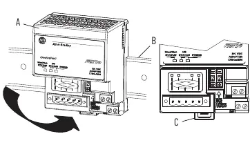
- Position the adapter on the DIN rail at a slight angle.
- Hook the lip on the rear of the adapter onto the top of the DIN rail.
- Rotate the adapter onto the rail and press down until it is flush.
- The locking tab should snap into position. If it does not, use a screwdriver to move the locking tab down while pressing the adapter flush, then release the tab to lock.
Mounting on an Existing System
- Remove the DeviceNet plug-in connector from the front.
- Disconnect any jumpered wiring.
- Use a screwdriver to open the module latching mechanism and remove the module from the base unit.
- Push the Flexbus connector to the right to unplug the backplane connection.
- Release the locking tab and remove the adapter.
Wiring
Important: Torque terminal screws to 0.8 N·m (7 lb·in). Do not wire more than two conductors on any single terminal. Power wiring must be less than 3m in length.
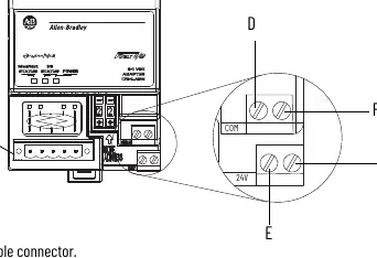
- DeviceNet Cable: Connect the wires to the removable connector as follows: BLK to -V, BLU to CAN low, WHT to CAN high, RED to +V, and Bare wire to Drain.
- Power: Connect +24V DC to terminal (E) and -V common to terminal (D). Terminals (F) and (G) are used to pass power to the next module in the series.
Configuration
Use the 2-position thumbwheel switch on the front of the module to set the node address. Valid settings range from 00 to 63. Press the + or - buttons to change the number.
Status Indicators
The module features LED indicators to help diagnose operation:
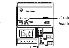
- Power: On indicates power is applied.
- Module/Network Status: Steady green indicates online and connected. Flashing red indicates a recoverable fault; steady red indicates a critical failure.
- I/O Status: Steady green indicates the device is operational and outputs are live. Flashing red indicates a fault.
Technical Specifications
- I/O Capacity: 8 modules.
- Power Supply: 19.2-31.2V DC.
- Communication Rate: 125 KB, 250 KB, 500 KB.
- Isolation Voltage: 50V (continuous), basic insulation.
- Dimensions: 87 x 68 x 69 mm.
Manufacturer information
Allen-Bradley
Practical help
Common problems
I/O size mismatch (Error 77)
Update the scanner's scan list to reflect the new I/O size or download the existing configuration to the adapter.
Adapter not locking on DIN rail
Use a screwdriver to move the locking tab down while pressing the adapter flush onto the rail, then release the tab.
Electric arc during insertion/removal
Ensure power is removed or the area is known to be nonhazardous before inserting or removing the module while backplane power is on.
Before use
- Verify the environment is Pollution Degree 2.
- Ensure the DIN rail is zinc-plated chromate-passivated steel.
- Check that power supply is 19.2-31.2V DC.
- Confirm wiring length is less than 3m.
- Ensure the enclosure has a minimum ingress protection rating of IP54 if used in Zone 2.
Specs in practice
- I/O Capacity
- The adapter supports up to 8 FLEX I/O modules.
- Communication Rate
- Supports 125 KB, 250 KB, and 500 KB baud rates, set via baud detection at power-up.
- Isolation Voltage
- 50V (continuous) basic insulation between power, Flexbus, and DeviceNet.
Images and diagrams
- DIN rail mounting: Hook the top lip, rotate, and press flush until the locking tab snaps.
- Wiring: Terminals D/E are for power input; F/G are for power pass-through.
Model compatibility
- Requires UKEX/ATEX/IECEx certified Rockwell Automation backplanes.
- Not intended for residential environments.

Manual page author
David Miller
Documentation analyst
Organizes user manual content into clear summaries, with attention to model details, product context, and everyday usability.