Electronics / Networking
Release Note for Allied Telesis Web-based Device GUI Version 2.12.x
Quick guide for Allied Telesis Web-based Device GUI version 2.12.x. Learn how to access the interface, update firmware, configure ACLs, set up Passpoint, and enable wireless Emergency Mode.
Table of contents
Manual images
Click an image to enlargeQuick Guide
This document provides release notes and configuration instructions for the Allied Telesis Web-based Device GUI version 2.12.x. It covers accessing the interface, updating the software, and configuring new features such as Access Control Lists (ACLs), Passpoint, and Emergency Mode.
Accessing the Web-based GUI
To access the GUI, you must first ensure an IP address is configured on an interface. If not already configured, use the command-line interface (CLI) to set an IP address:
- Enable mode: enable
- Configure terminal: configure terminal
- Interface setup: interface vlan1
- Set IP: ip address 192.168.1.1/24
Default IP Addresses:
- Switches: 169.254.42.42
- AR-Series: 192.168.1.1
Open a web browser and navigate to the IP address. The default username is manager and the default password is friend.
Updating the GUI
Updating on Switches
- Obtain the GUI file (e.g., awplus-gui_552_27.gui) from the Allied Telesis Software Download center.
- Log into the GUI.
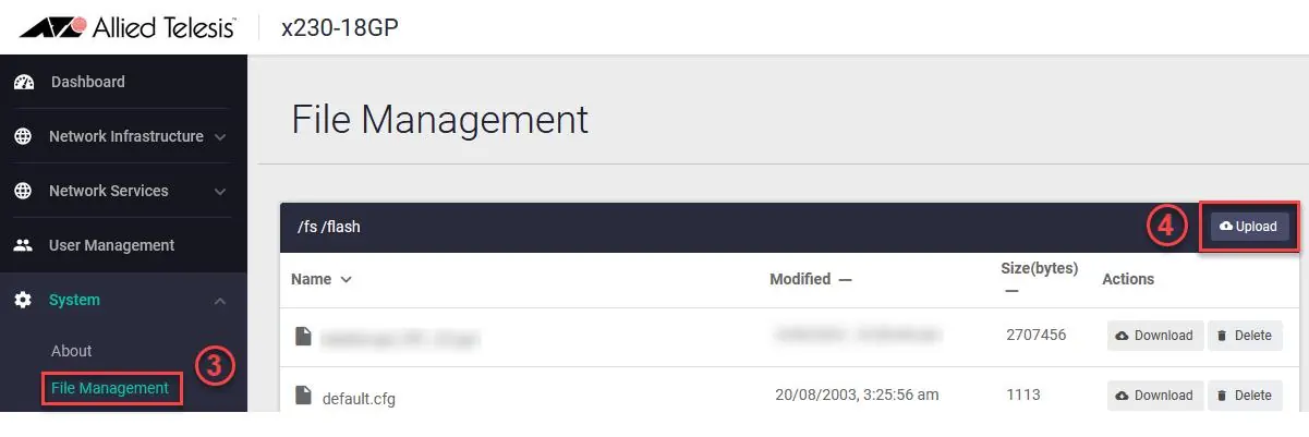
- Navigate to System > File Management.
- Click Upload and select the downloaded file.
- Reboot the switch or restart the HTTP service via CLI using no service http followed by service http.
Updating on AR-Series Devices
- Access the CLI via Serial console or SSH.
- Run the command: update webgui now.
- Verify the update by checking the version on the System > About page in the GUI.
New Features and Enhancements
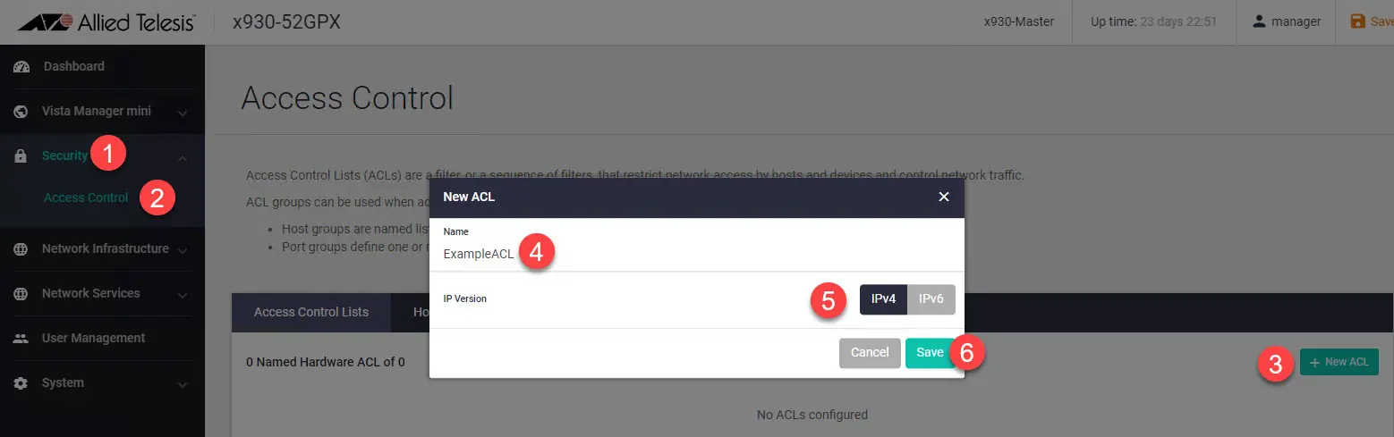
Creating Access Control Lists (ACLs)
You can create IPv4 and IPv6 hardware ACLs to allow or block traffic. Navigate to the Security menu and select Access Control to define host groups, port groups, and apply filters to interfaces.
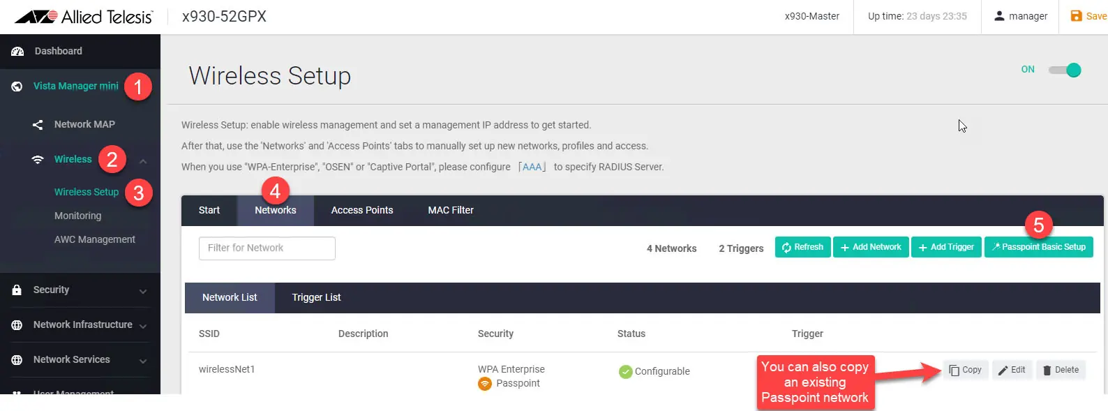
Simplified Passpoint Setup
On devices acting as a wireless controller, use the Network page to set up a new Passpoint network. You can use the Passpoint Basic Setup button to create a new network or copy an existing one.
Wireless Emergency Mode
Emergency Mode makes your wireless network available to the public during emergencies. You can activate this using a pre-prepared USB stick:
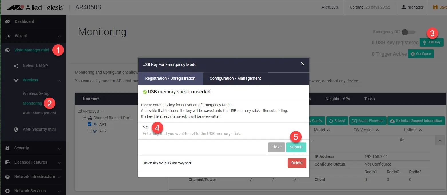
- Insert an empty USB stick into the controller.
- Enter a key and enable the feature in the GUI.
- Remove the USB stick.
- To activate Emergency Mode, simply insert the USB stick into the device. The port LEDs will blink to indicate activation.
Manufacturer information
Allied Telesis
Practical help
Common problems
Cannot access the GUI
Ensure an IP address is configured on the interface. Use the default IP (169.254.42.42 for switches or 192.168.1.1 for AR-Series) if not configured.
Emergency Mode not activating
Ensure the USB key matches the key registered on the device and that the feature is enabled in the GUI.
Before use
- Ensure the device is running compatible AlliedWare Plus firmware (5.5.0-x.x or later).
- For switches: Download the correct GUI file from the Allied Telesis Software Download center.
- For AR-Series: Ensure firewall rules permit external services if required.
- Have the default credentials (manager/friend) ready for initial login.
Specs in practice
- Default Username
- manager
- Default Password
- friend
- Switch Default IP
- 169.254.42.42
- AR-Series Default IP
- 192.168.1.1
Images and diagrams
- The GUI provides a dashboard for monitoring system information, port status, and traffic.
- The Access Control page allows for the creation and management of IPv4 and IPv6 hardware ACLs.
- The File Management page is used to upload new GUI firmware files.
Model compatibility
- GUI version 2.12.0 requires AlliedWare Plus firmware 5.5.0-x.x, 5.5.1-x.x, or 5.5.2-x.x.
- Passpoint setup requires firmware 6.0.1-5.1 or later on AT-TQ5403, AT-TQm5403, and AT-TQ5403e APs.
- Channel Blanket VAP limits vary by AP model (TQ5403/TQ5403e vs TQ6602).

Manual page author
David Miller
Documentation analyst
Organizes user manual content into clear summaries, with attention to model details, product context, and everyday usability.