Electronics / Networking
User Manual for FortiGate 200F Series
Quick guide for the FortiGate 200F Series. Includes installation instructions, rack mounting, desktop setup, port descriptions, LED indicators, and safety information.
Quick answers from the manual
Quick answer
- The FortiGate 200F Series is a network security appliance. This guide covers installation, port identification, and safety requirements. p. 1, 4, 8, 9
Key actions
- Rack Installation p. 8
- Desktop Installation p. 9
- SFP Installation p. 11
First start
- Connect power cables to grounded outlets. Connect management port (default IP 192.168.1.99) to configure. p. 4, 9, 10
Problems and fixes
Major alarm (Red LED)
Check system status and logs for critical errors.
p. 4Maintenance and reset
- Use the BLE/RESET button to restore factory default and BLE settings. p. 4
Technical specifications
| Parameter | Value | Meaning | Pages |
|---|---|---|---|
| Power Input | 100-240V AC, 50/60 Hz, 2-1.2A | Redundant hot swappable power supplies. | p. 6 |
| Management IP | 192.168.1.99 | Default IP for management port. | p. 4 |
Where to find it in the PDF
- Box Includes p. 2, 3
- Front Panel p. 4, 5
- Rear Panel p. 6, 7
- Installation p. 8, 9, 11
Table of contents
Manual images
Click an image to enlargeQuick guide from the manual
The FortiGate 200F Series is a network security appliance. This guide provides essential information for installation, initial setup, and understanding the device's status indicators. Always ensure the device is installed in a well-ventilated area with at least 1.5 inches of clearance for airflow.
Box Includes
Ensure your package contains the following items:
- FortiGate 200F/201F unit
- Information Supplement
- QuickStart Guide
- 2x AC Power Cables
- Console Cable (USB to RJ45)
- Ethernet Cable
- Rubber Feet
- 8x Bracket Screws
- 2x Mounting Brackets
Front Panel
The front panel features various ports and LED indicators:
- LED Indicators: Status, Alarm, HA, and Power.
- Ports: USB 3.0 server port, Console (RJ45), HA (RJ45), MGMT (RJ45), and network ports (RJ45 and SFP/SFP+).
- BLE/RESET: Restores factory default and BLE settings.
Installation
Rack Installation
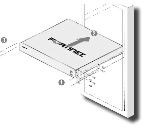
- Attach the provided rack-mount brackets and screws to the device.
- Position the device and slide it into a standard 19-inch rack.
- Fasten the rack screws to secure the device.
- Warning: It is recommended that two people install the device for safety.
Desktop Installation
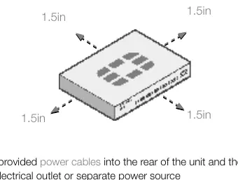
- Place the unit on a flat, clean, and stable surface.
- Ensure there is at least 1.5 inches of clearance around the device for adequate airflow.
- Plug the provided power cables into the rear of the unit and then into a grounded electrical outlet.
SFP Installation
To install SFP transceivers:
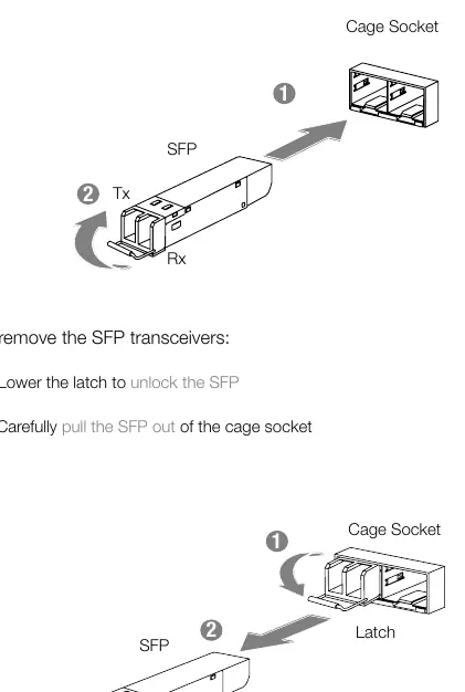
- Slide the SFP into the cage socket until it clicks into place.
- Lift the latch to lock the SFP.
To remove SFP transceivers:
- Lower the latch to unlock the SFP.
- Carefully pull the SFP out of the cage socket.
Safety and Warnings
- Operating Temperature: 0°C to 40°C.
- Power: 100-240V AC, 50/60 Hz, 2-1.2A.
- Battery: Risk of explosion if replaced by an incorrect type. Dispose of used batteries according to local regulations.
- Shock Hazard: Disconnect all power sources before servicing.
Manufacturer information
Fortinet, Inc.
Practical help
Common problems
Unit not booting or status LED off
Check power supply connections and ensure the power outlet is active.
No network link
Verify cable connection and ensure SFP transceivers are properly seated and locked.
HA failure
Check the HA port connection and ensure the HA cluster is configured correctly.
Before use
- Ensure 1.5 inches of clearance above and below the device for airflow.
- Verify power source is 100-240V AC.
- Use a grounded electrical outlet.
- Install rack brackets if mounting in a 19-inch rack.
- Place on a flat, clean, and stable surface if using as a desktop unit.
Images and diagrams
- Front Panel: Identifies LED indicators (Status, Alarm, HA, Power) and port locations (USB, Console, MGMT, HA, Network).
- Rear Panel: Shows redundant power supply inputs.
Model compatibility
- Mounts in standard 19-inch rack.
- Requires grounded electrical outlet.

Manual page author
David Miller
Documentation analyst
Organizes user manual content into clear summaries, with attention to model details, product context, and everyday usability.