Electronics / Networking
FortiProxy 2000E QuickStart Guide
Quick start guide for the FortiProxy 2000E network appliance. Includes instructions for rack mounting, initial configuration via web browser or CLI, LED status indicators, and safety warnings.
Quick answers from the manual
Quick answer
- The FortiProxy 2000E is a network appliance. Initial setup is performed via a web browser at 192.168.1.99 (admin/no password) or via CLI using a console cable (9600, 8, N, 1). p. 4, 5
Key actions
- Connect to GUI p. 4
- Connect to CLI p. 5
First start
- Connect power and network, then access via web browser or console. p. 4, 5
Problems and fixes
Power Fail LED flashing red
Power supply failure.
p. 6
Information LED flashing red (1Hz)
Fan failure.
p. 6Technical specifications
| Parameter | Value | Meaning | Pages |
|---|---|---|---|
| Power | 100-240V AC, 9.8-5A, 50/60Hz | Power input requirements | p. 6 |
Where to find it in the PDF
- Box Contents p. 3
- Installation p. 5
- Device Guide p. 6, 7
Table of contents
Manual images
Click an image to enlargeQuick guide from the manual
This guide provides the essential steps to install and configure your FortiProxy 2000E. For detailed safety information and regulatory compliance, please refer to the full documentation provided with the device.
Box Includes
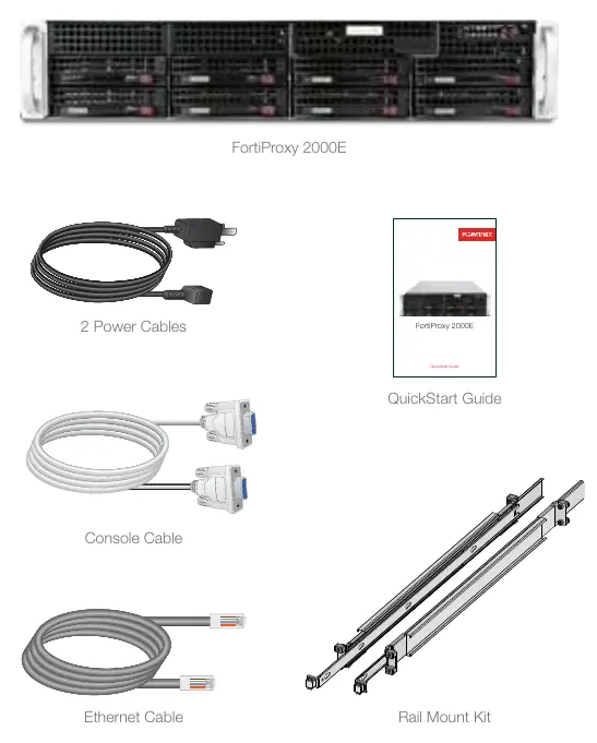
- FortiProxy 2000E unit
- 2 Power Cables
- Ethernet Cable
- Console Cable
- Rail Mount Kit
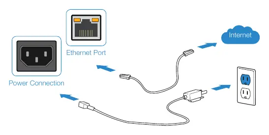
Basic Connections
Connect your device to a power outlet and an Internet connection (usually a modem or another network device). Ensure the power source is grounded.
Setup Options
Web Browser (GUI)
- Connect an Ethernet cable to Port1.
- Configure your management computer to the same subnet as the FortiProxy unit (IP: 192.168.1.XX, Netmask: 255.255.255.0).
- Visit https://192.168.1.99 in your web browser.
- Login using username admin and no password.
- Configure your device and save settings.
- Register your device from the dashboard.
Terminal Emulation (CLI)
- Connect the console cable to the device's console port and your management computer.
- Start a terminal emulation program with the following settings: Baud Rate: 9600, Data bits: 8, Parity: None, Stop bits: 1, Flow Control: None.
- Press Enter to connect.
- Login using username admin and no password.
Installation
The unit is designed for mounting in a standard 19-inch rack.
- Caution: Electrostatic discharge (ESD) can damage equipment.
- It is recommended that two or more people install the unit into the rack.
- Attach inner slide rails to the unit using M4 flat head screws.
- Attach outer slide rails to the rack.
- Slide the unit into the rack until the locking tabs click into place.
- Connect power cables to the rear of the unit and then to grounded electrical outlets or a UPS/PDU.
Device Guide
The front and rear panels feature various ports and LED indicators:
- Power Fail LED: Flashing Red indicates a power supply failure.
- Information LED: Flashing Red (1Hz) indicates fan failure; Solid Red indicates overheat; Flashing Red (0.25Hz) indicates power supply failure.
- Ethernet Ports: Green indicates connection; Flashing Green indicates activity.
- HDD Status: Red indicates HDD failure.
Safety and Warnings
Ensure sufficient airflow around the unit. Do not place heavy objects on the unit. Disconnect power supply cords before servicing. Each power cable should be connected to a different power source to ensure redundancy.
Manufacturer information
Fortinet, Inc.
Practical help
Common problems
Power Fail LED flashing red
A power supply has failed. Check power connections and source.
Information LED flashing red (1Hz)
Fan failure detected. Ensure the unit is not overheating and check for obstructions.
Information LED solid red
System is in an overheat condition. Ensure sufficient airflow around the unit.
HDD Status LED red
Hard disk drive has failed.
Before use
- Ensure two people are available for rack installation.
- Verify power source is grounded.
- Configure management computer to 192.168.1.XX subnet.
- Have a terminal emulation program ready for CLI access.
- Ensure sufficient room around the unit for air flow.
Specs in practice
- Baud Rate: 9600
- Required speed for serial console connection.
- Default IP: 192.168.1.99
- Address used to access the web GUI.
- Power: 100-240V AC
- Supported input voltage range.
Images and diagrams
- Front panel: HDD slots, power button, and status LEDs.
- Rear panel: Power inputs, Ethernet ports, console port, and SFP/SFP+ ports.
Model compatibility
- Requires standard 19-inch rack for mounting.

Manual page author
Michael Turner
Technical manual editor
Reviews PDF manuals for structure, safety notes, and practical product details so readers can find the right information quickly.