Electronics / Networking
Fortinet FortiEdge 200F QuickStart Guide
QuickStart guide for the Fortinet FortiEdge 200F network security appliance. Includes instructions for physical installation, port connections, LED status indicators, and initial configuration via GUI or CLI.
Quick answers from the manual
Quick answer
- The FortiEdge 200F is a network security appliance. To set it up, connect to the MGMT port, set your computer IP to 192.168.1.1, and access https://192.168.1.99 in a browser using 'admin' as the username with no password. p. 9
Key actions
- Rack Installation p. 7
- Initial GUI Setup p. 9
First start
- Connect MGMT port to PC, set PC IP to 192.168.1.1, browse to 192.168.1.99, login as admin (no password). p. 9
Problems and fixes
Cannot access GUI
Check IP settings on management computer (192.168.1.1/255.255.255.0).
p. 9Technical specifications
| Parameter | Value | Meaning | Pages |
|---|---|---|---|
| Power Input | 100-240V AC, 50/60 Hz | Redundant hot swappable power supplies | p. 6 |
Where to find it in the PDF
- Box Includes p. 4
- Front Panel p. 5
- Installation p. 7
Table of contents
Manual images
Click an image to enlargeQuick guide from the manual
This document provides the essential steps to install and configure your Fortinet FortiEdge 200F appliance. It covers physical installation, basic cabling, and initial setup via the web-based GUI or Command Line Interface (CLI).
Box Includes
Ensure your package contains the following items:
- FortiEdge 200F unit
- QuickStart Guide
- 2x AC Power Cables
- 1x Console Cable (USB to RJ45)
- 1x Ethernet Cable
- 2x Mounting Brackets
- 8x Bracket Screws
- 4x Rubber Feet
Front Panel and LED Indicators
The front panel features various ports and LED indicators to monitor the device status:
- STATUS: Green (Operating normally), Flashing Green (Booting up), Red (Major alarm).
- POWER: Green (On), Red (One supply providing power), Off (Off).
- HA: Green (Operating in HA cluster), Red (HA failover), Off (HA disabled).
- ALARM: Red (Major alarm), Amber (Minor alarm), Off (No alarms).
The device includes RJ45 management ports (MGMT1/MGMT2), console port, USB port, and various network ports (RJ45 and SFP/SFP+).
Installation
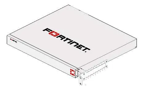
Rack Installation
- Attach the provided rack-mount brackets and screws to the device.
- Position the device and slide it into a standard 19-inch rack.
- Fasten the rack screws to secure the device.
Warning: We recommend that two people install the device. Allow at least 1.5 inches of space above and below the device for airflow.
Desktop Installation
- Place the unit on a flat, clean, and stable surface.
- Ensure there is at least 1.5 inches of clearance for adequate airflow.
- Plug the provided power cables into the rear of the unit and then into a grounded electrical outlet.
Basic Connections
Connect the device to a power outlet using the provided power cables. We recommend connecting to an uninterruptible power supply (UPS) to protect against power outages.
Device Setup
GUI Setup
- Connect the MGMT port to your computer using the supplied Ethernet cable.
- Set your computer's IP address to 192.168.1.1 and subnet mask to 255.255.255.0.
- Open a web browser and visit https://192.168.1.99.
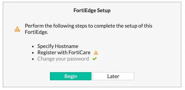
- Log in with username admin and leave the password blank.
- Follow the prompts to create a new password and complete the setup.
CLI Setup
- Connect the Console Port to your computer using the console cable.
- Start a terminal emulation program (e.g., PuTTY) with settings: Baud rate 9600, Data bits 8, Parity None, Stop bits 1, Flow control None.
- Log in with username admin and no password.
- Follow the prompts to set a new password and configure the appliance.
Manufacturer information
Fortinet, Inc.
Practical help
Common problems
Cannot access the GUI
Ensure your management computer is configured with a static IP in the 192.168.1.x range (e.g., 192.168.1.1) and is connected to the MGMT port.
Device not powering on
Verify that both power cables are securely connected to the unit and a grounded electrical outlet.
Before use
- Verify all box contents are present
- Ensure 1.5 inches of clearance for airflow
- Use a grounded electrical outlet
- Have a computer ready for initial configuration
- Ensure you have an Ethernet cable for the MGMT port
Specs in practice
- MGMT1 Default IP
- 192.168.1.99
- MGMT2 Default IP
- 192.168.2.99
Images and diagrams
- Front panel diagram shows LED locations and port layout
- Rear panel diagram shows redundant power supply inputs
- Rack installation diagram shows bracket attachment and rack mounting
Model compatibility
- Requires standard 19-inch rack for rack mounting
- SFP transceivers may not be included with all models

Manual page author
Michael Turner
Technical manual editor
Reviews PDF manuals for structure, safety notes, and practical product details so readers can find the right information quickly.