Power / Solar Panels
User Manual for Allpowers 20A Solar Charger Controller
A comprehensive guide for the Allpowers 20A Solar Charger Controller. Includes installation instructions, wiring order, LCD menu settings, troubleshooting tips, and technical specifications.
Quick answers from the manual
Quick answer
- The Allpowers 20A Solar Charger Controller is an automatic 12V/24V regulator. Always connect the battery first to ensure correct system voltage detection. p. 1
Key actions
- Connect the battery first, then the solar panel, then the load. p. 1
First start
- Connect the battery to the controller. The LCD will light up and detect the system voltage automatically. p. 1
Problems and fixes
Battery low
Charge the battery.
p. 1
Load short circuit
Check load wiring.
p. 1Maintenance and reset
- To reset settings, use the menu navigation to restore factory defaults if available, or disconnect and reconnect the battery to reboot. p. 1
Technical specifications
| Parameter | Value | Meaning | Pages |
|---|---|---|---|
| Rated Current | 20A | Maximum charging/discharging current | p. 1 |
| Max Input | <50V | Maximum solar panel voltage | p. 1 |
Where to find it in the PDF
- Main Manual Page p. 1
Table of contents
Manual images
Click an image to enlargeQuick guide from the manual
The Allpowers 20A Solar Charger Controller is designed for 12V/24V solar systems. Crucial: Always connect the battery first to allow the controller to detect the system voltage automatically. Follow the wiring sequence: Battery -> Solar Panel -> Load.
Installation and Wiring
Proper installation is essential for the safety and longevity of the device. Follow these steps in order:
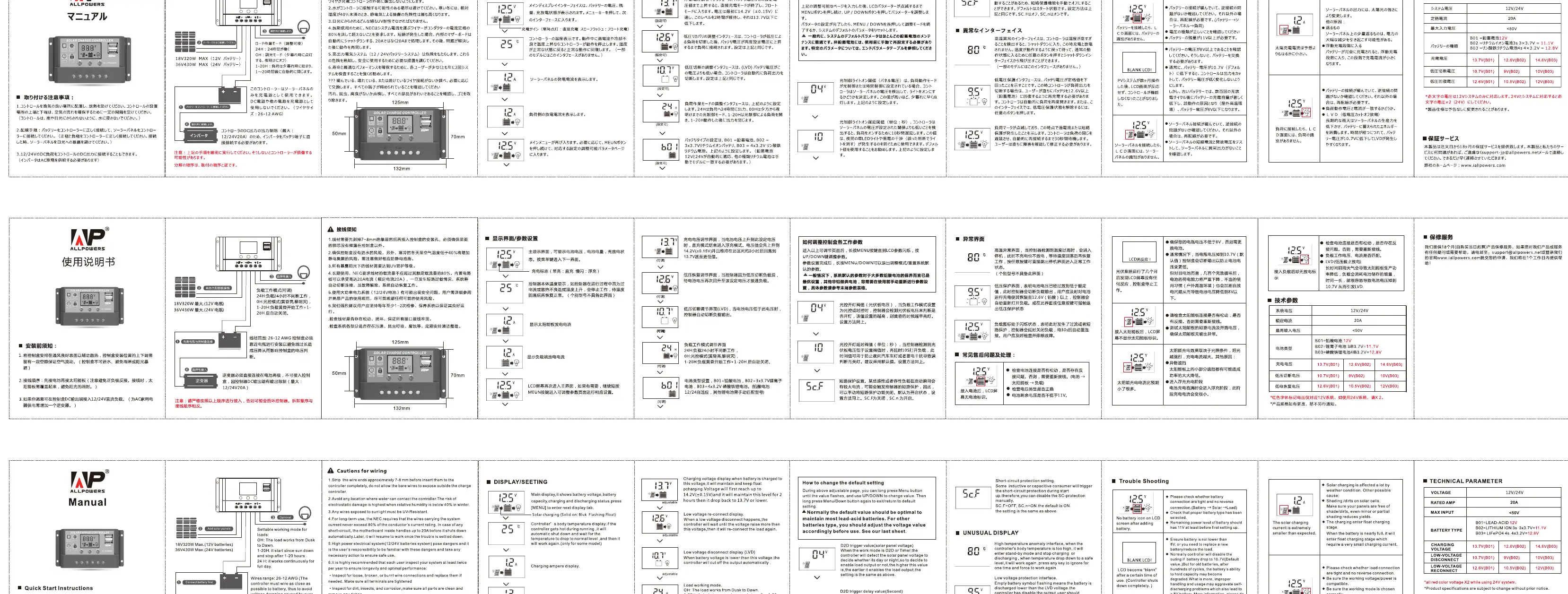
- Battery Connection: Connect the battery to the charge regulator (plus and minus). The controller will automatically detect the system voltage (12V or 24V).
- Solar Panel Connection: Connect the solar module to the regulator (plus and minus). Ensure the open-circuit voltage does not exceed the maximum input limit.
- Load Connection: Connect the consumer (load) to the regulator (plus and minus).
- Reverse Order: When uninstalling, follow the reverse order (Load -> Solar Panel -> Battery).
Operation and Settings
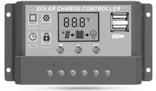
The controller features an LCD display and three buttons (MENU, UP, DOWN) for configuration:
- Menu Navigation: Press the MENU button to cycle through different display screens (Voltage, Battery Level, Load, etc.).
- Adjusting Settings: When on a setting screen, hold the MENU button to enter edit mode. Use the UP/DOWN buttons to change values, then press MENU to save.
- Display Icons: The screen shows icons for the solar panel, battery, and load, indicating current status and flow.
Troubleshooting
If you encounter issues, check the following:
- Battery Low: The battery voltage is too low; the controller will cut off output. Charge the battery.
- Load Short Circuit: The load is shorted. Check the wiring and connections.
- Overheating: If the controller temperature is too high, it will automatically shut down. Ensure the device is installed in a well-ventilated area.
- No Display: Check battery connections and polarity.
Technical Specifications
- Rated Current: 20A
- System Voltage: 12V/24V Auto
- Max Solar Input:<50V
- USB Output: 5V/2A
- Operating Temperature: -35°C to +60°C
Safety Precautions
- Do not exceed the maximum input voltage of 50V.
- Ensure the controller is installed in a cool, dry, and well-ventilated environment.
- Do not disassemble the unit.
- Keep the controller away from water and moisture.
Manufacturer information
ALLPOWERS
Practical help
Common problems
Battery icon flashing
Battery voltage is low; the controller has cut off output to protect the battery. Charge the battery.
Load icon flashing
Load short circuit or overload detected. Check the load wiring and reduce the load.
Controller not turning on
Check if the battery is connected correctly and if the voltage is within the operating range.
Before use
- Ensure the battery is fully charged or functional.
- Verify that the solar panel voltage does not exceed 50V.
- Check that all wiring connections are tight and polarity is correct.
- Ensure the installation environment is well-ventilated.
Specs in practice
- 12V/24V Auto
- The controller automatically detects and adapts to the connected battery system voltage.
- Max Input <50V
- The solar panel array voltage must not exceed 50V, or the controller may be damaged.
- Rated Current 20A
- The maximum current the controller can handle for charging and load output.
Images and diagrams
- The wiring sequence is critical: 1. Battery, 2. Solar Panel, 3. Load.
Model compatibility
- Compatible with 12V and 24V lead-acid batteries.

Manual page author
David Miller
Documentation analyst
Organizes user manual content into clear summaries, with attention to model details, product context, and everyday usability.