Power / Solar Charge Controllers
User Manual for EPEVER Tracer-AN G3 MPPT Solar Charge Controller
Quick guide for the EPEVER Tracer-AN G3 series MPPT solar charge controller. Includes installation steps, wiring diagrams, battery settings, load mode configuration, and troubleshooting.
Table of contents
Manual images
Click an image to enlargeQuick guide from the manual
The EPEVER Tracer-AN G3 series is an MPPT solar charge controller designed for RVs, household systems, and field monitoring. It features advanced MPPT technology to maximize energy harvest and supports various battery types, including lithium. Important: Always connect the system in the order of battery, then load, then PV array. Disconnect in the reverse order.
Installation
The controller must be installed indoors in a well-ventilated area. Ensure at least 150mm of clearance above and below the unit for airflow. Do not install in humid, corrosive, or flammable environments.

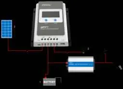

Wiring steps:
- Connect the battery to the battery terminals.
- Connect the load to the load terminals.
- Connect the PV array to the PV terminals.
- Ensure all connections are tight to prevent overheating.
- Use appropriate external fast-acting fuses or breakers on the battery side.
The controller is a common-negative device, meaning negative terminals of the PV array, battery, and load can be grounded simultaneously.
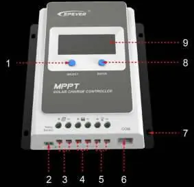
LCD and Settings
The LCD provides real-time status and allows for parameter configuration using the SELECT and ENTER buttons.
- Browsing: Press the SELECT button to cycle through interfaces.
- Setting Mode: Press and hold the ENTER button for 5 seconds to enter setting mode. Use SELECT to change parameters and ENTER to confirm.
- Battery Type: Supports Sealed, Gel, Flooded, and Lithium (LiFePO4, Li(NiCoMn)O2) batteries. Select 'USE' to manually configure voltage parameters.
- Load Modes: Configurable via the load type interface. Options include Light ON/OFF, timer-based modes, and manual control.
Protection and Troubleshooting
The controller includes comprehensive electronic protections, such as PV over-current, short-circuit, reverse polarity, and battery over-voltage/over-discharging protection. If a fault occurs, the LCD will display error codes or blink icons. For example, if the battery voltage is too low, ensure it is at least 8V to activate the controller. If the load fails, check for short circuits or overloads.
Maintenance
Recommended maintenance tasks at least twice a year:
- Clear dirt and fragments from the radiator to ensure proper airflow.
- Inspect all wires for insulation damage or corrosion.
- Verify that the indicator display matches actual operation.
- Tighten terminal screws to the suggested torque.
- Check the lightning arrester condition if installed.
Practical help
Common problems
PV array open-circuit
Confirm that the PV array connection is correct and tight.
Controller not working / Battery voltage low
Check the battery voltage; it must be at least 8V to activate the controller.
Load failure (Overload/Short-circuit)
Reduce the number of electric devices or check the load connection, then restart the controller or press the button to clear the fault.
Battery overheating
The controller will stop working when the battery temperature exceeds 65°C. It will resume automatically when the temperature drops below 55°C.
Before use
- Ensure the installation environment is well-ventilated and free from moisture, salt spray, or corrosive substances.
- Verify that the PV array open-circuit voltage does not exceed the controller's maximum limit (46V or 92V depending on the model).
- Prepare appropriate external fast-acting fuses or breakers for the battery and PV array.
- Ensure all power connections are tight to prevent excessive heating.
- Wear eye protection when installing open-type lead-acid batteries.
Specs in practice
- Rated Charging Current
- The maximum current the controller can handle from the PV array (e.g., 10A, 20A, 30A, 40A).
- MPPT Voltage Range
- The voltage range within which the controller can track the maximum power point of the PV array.
- System Voltage
- The nominal voltage of the battery bank (12V/24V auto-recognition).
Images and diagrams
- Wiring order: Always connect the battery first, then the load, and finally the PV array.
- Grounding: The controller is a common-negative device; negative terminals can be grounded simultaneously.
Model compatibility
- Supports Lead-acid (Sealed, Gel, Flooded) and Lithium-ion batteries.
- Tracer-AN G3 BLE models include a built-in Bluetooth module for app connectivity.
- Requires external temperature sensor for accurate battery temperature compensation.

Manual page author
Michael Turner
Technical manual editor
Reviews PDF manuals for structure, safety notes, and practical product details so readers can find the right information quickly.