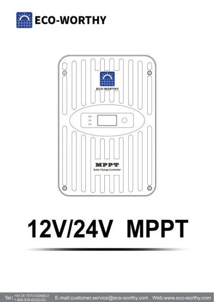
Power / Solar Charge Controllers
ECO-WORTHY 12V/24V MPPT Solar Charge Controller User Manual
Quick guide for the ECO-WORTHY 12V/24V MPPT Solar Charge Controller. Includes installation steps, wiring diagrams, battery charging settings, and troubleshooting.
Table of contents
Manual images
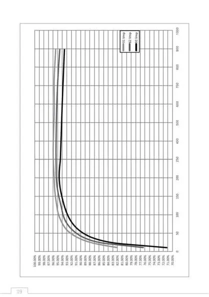
Click an image to enlargeQuick guide from the manual
This manual provides installation and operation instructions for the ECO-WORTHY MPPT Solar Charge Controller. The controller is designed to regulate solar power for 12V or 24V battery systems. Always ensure the solar array voltage does not exceed the controller's maximum input voltage (100V or 150V depending on the model).
Safety Information
- Disconnect all power sources before installing or adjusting the controller.
- Use insulated tools when working with batteries.
- Do not install in enclosures with vented/flooded batteries.
- Ensure proper ventilation; the heatsink can become hot during operation.
- The controller must be installed by a qualified technician in accordance with local electrical regulations.
Installation
Mounting: Install the controller indoors in a vertical position (fins up and down). Allow at least 15 cm (6 in) of space above and below, and 10 cm (4 in) at the sides for airflow.
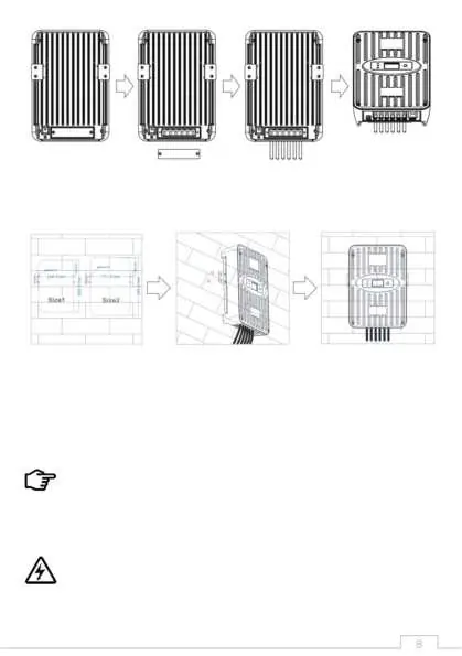
Wiring Sequence:
- Connect the battery to the controller.
- Connect the solar panel to the controller.
- Always disconnect in the reverse order (solar first, then battery).
Ensure all power connections are tight to prevent overheating.
Operation
The controller features a 1.3-inch OLED display and a function button. Users can set the battery type using the preset parameters. For custom settings, optional accessories are required.

Battery Charging: The controller uses a 4-stage algorithm for lead-acid batteries (CC, CV, CF, Equalization) and a 2-stage process for Lithium-ion batteries.
Load Control: The load terminals are for DC loads only. Do not connect AC inverters to the load terminals; connect them directly to the battery.
Troubleshooting
- No LED indications: Check battery voltage (must be >10V) and verify wiring connections, fuses, and breakers.
- Not charging: Ensure solar input voltage is higher than battery voltage. Check fuses and breakers.
- Battery low/empty: Increase solar panel quantity or battery capacity.
Technical Specifications
The controller supports 12V or 24V systems with an operating range of 9-30V. Models include NS24L30, NS24L40, NS24H50, and NS24H60, with charging currents ranging from 30A to 60A.
Practical help
Common problems
No LED indications / Controller appears off
Check battery voltage with a multi-meter (must be 10V or greater). Check wiring connections, fuses, and breakers.
MPPT is not charging the battery
Check fuses, breakers, and wiring. Ensure solar array voltage is higher than battery voltage.
Battery remains low or empty for a long time
Increase the quantity of solar panels to generate more energy or increase battery capacity.
Before use
- Verify battery voltage is at least 10V.
- Ensure solar array open-circuit voltage (Voc) does not exceed controller limits.
- Use insulated tools.
- Ensure proper ventilation (15cm above/below, 10cm sides).
- Check for correct polarity before applying power.
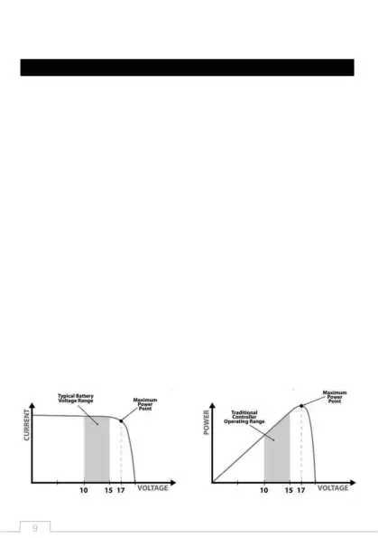
Specs in practice
- Nominal Battery Voltage
- 12V or 24V (Auto-detect at start-up).
- Max. PV Open-Circuit Voltage
- 100V or 150V depending on model; do not exceed this limit.
- Max. Battery Charging Current
- 30A, 40A, 50A, or 60A depending on the specific model.
- Conversion Efficiency
- 97% peak efficiency.
Images and diagrams
- Wiring sequence: Connect battery first, then solar panel.
- Heat sink orientation: Must be vertical (fins up and down).
Model compatibility
- Compatible with 12V/24V systems.
- Supports Lead-acid (Gel, Sealed, Flooded, AGM) and Lithium-ion (LiFePO4) batteries.
- Do not connect AC inverters to load terminals.

Manual page author
David Miller
Documentation analyst
Organizes user manual content into clear summaries, with attention to model details, product context, and everyday usability.