Power / Solar Charge Controllers
User Manual for ECO-WORTHY 20A MPPT Solar Charge Controller
Quick guide for the ECO-WORTHY 20A MPPT Solar Charge Controller. Learn about installation, wiring, output modes, parameter settings, and troubleshooting.
Quick answers from the manual
Quick answer
- The ECO-WORTHY 20A MPPT Solar Charge Controller is a 12V/24V device that manages solar charging. It features 5 output modes, LCD monitoring, and 3-stage charging. p. 1
Key actions
- Wiring order: Connect Battery first, then Load, then Solar panel. p. 4
- Disconnection order: Disconnect Solar panel first, then Battery, then Load. p. 4
First start
- Connect the battery first to power on the controller and allow it to detect the system voltage. p. 5
Problems and fixes
No display on LCD
Check battery connection and controller fuse.
p. 9
Battery cannot be charged
Check battery condition, polarity, and voltage settings.
p. 9Maintenance and reset
- To reset system voltage, disconnect the controller for 20 seconds. p. 5
Technical specifications
| Parameter | Value | Meaning | Pages |
|---|---|---|---|
| Max Current | 20A | Maximum charge and discharge current. | p. 2 |
| System Voltage | 12V/24V DC | Rated system voltage. | p. 2 |
Where to find it in the PDF
- Features p. 1
- Specifications p. 2
- Wiring Diagram p. 2
- Terminal Block p. 3
- Troubleshooting p. 8, 9
Table of contents
Manual images
Click an image to enlargeQuick guide from the manual
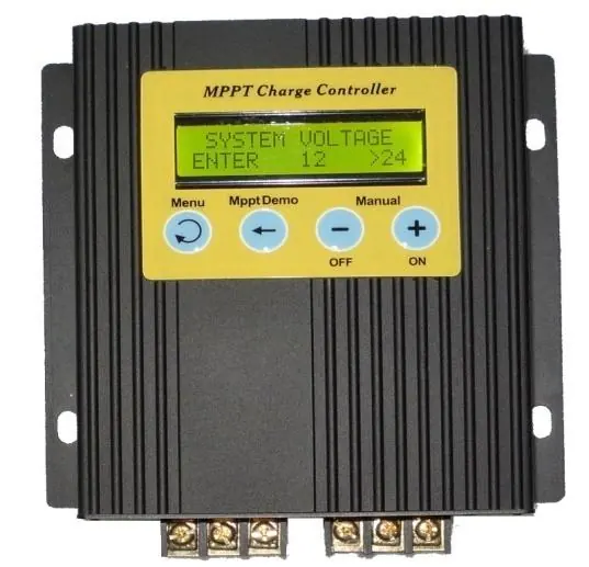
The ECO-WORTHY 20A MPPT Solar Charge Controller is designed for 12V/24V solar power systems. It features a 3-stage charging algorithm, LCD monitoring, and five configurable output modes. Important: Always connect the battery first to ensure the controller detects the system voltage correctly.
Installation and Wiring
The terminal block is numbered 1 through 6 from left to right. Ensure all connections are secure and polarity is correct.
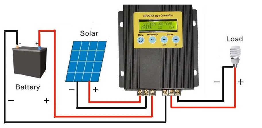
- 1: Solar panel "+"
- 2: Solar panel "-"
- 3: Battery "+"
- 4: Battery "-"
- 5: Load "+"
- 6: Load "-"
Wiring Order:
- Connect Battery (1st)
- Connect Load (2nd)
- Connect Solar panel (3rd)
Disconnection Order:
- Disconnect Solar panel (1st)
- Disconnect Battery (2nd)
- Disconnect Load (3rd)
Use 4mm2 copper core cable for solar panel connections and 6mm2 cable for battery connections. Install earth and lightning protection as required.
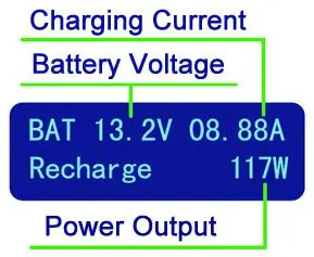
LCD Display and Buttons
The LCD provides real-time data including battery voltage, charging current, power output, and controller status. Use the buttons to navigate:
- MENU: Switch between operating settings.
- MPPT DEMO: Track max power point or cycle through setting fields.
- +: Manual ON or increase values.
- -: Manual OFF or decrease values.
Output Modes
The controller offers five output modes to manage the load:
- MODE 1 (Manual): Load turned on/off via buttons.
- MODE 2 (Always): Constant output to load terminals.
- MODE 3 (Light sensor + Timer): Load turns on when dark and off after a set number of hours.
- MODE 4 (Begin/End Time): Load turns on/off at specific scheduled times.
- MODE 5 (Light sensor + End Time): Load turns on when dark and off at a specific scheduled time.
Parameter Settings
To adjust settings, press the MENU button until the desired parameter (e.g., ABSORB, FLOAT, OVER, RESTART, CLOCK SET) appears on the display. Use + or - to change values and MENU to save and return to the main screen.
Troubleshooting
If you encounter issues, check the following:
- No display: Verify battery connection and check if the controller fuse is intact.
- Battery not charging: Ensure battery is in good condition, solar panel polarity is correct, and charging voltage settings are appropriate.
- No discharge: Ensure battery voltage is higher than the over-discharge protection setting.
Practical help
Common problems
Battery cannot be charged
Check battery condition, verify solar panel polarity, and ensure over-charging voltage settings are correct.
No display on LCD
Check if the battery is connected correctly and inspect the controller fuse.
No discharge
Ensure the battery voltage is higher than the configured over-discharge protection voltage.
Before use
- Ensure solar panel voltage is within the controller's acceptable range (15-50V DC).
- Ensure battery voltage is within the controller's acceptable range.
- Use 4mm2 copper core cable for solar panel connection.
- Use 6mm2 cable for battery connection.
- Install earth and lightning protection.
- Connect the battery first to allow the controller to detect system voltage.
Specs in practice
- Rated system voltage
- 12V/24V DC auto-detection.
- Max solar panel power
- 300W for 12V systems / 600W for 24V systems.
- Protect class
- IP22 (indoor use recommended).
Images and diagrams
- Terminal block 1-2: Solar panel input.
- Terminal block 3-4: Battery connection.
- Terminal block 5-6: Load output.
Model compatibility
- Compatible with 12V and 24V battery systems.
- Not suitable for systems exceeding 50V open circuit voltage.

Manual page author
Michael Turner
Technical manual editor
Reviews PDF manuals for structure, safety notes, and practical product details so readers can find the right information quickly.