Electronics / RFID Barcode Scanners
User Manual for Renogy Voyager 20A PWM Waterproof Controller
Quick guide for the Renogy Voyager 20A PWM Waterproof Controller. Learn about installation, battery type selection, LED error codes, and technical specifications.
Quick answers from the manual
Quick answer
- The Renogy Voyager 20A is a waterproof PWM charge controller for 12V solar systems. Always connect the battery to the controller first, then the solar panels. p. 9
Key actions
- Select battery type p. 11
- Install controller p. 9
First start
- Connect battery first, then solar panels. The controller will run a self-quality check mode automatically. p. 9, 11
Problems and fixes
b01
Solar good, BV < 3V
p. 13
b03
Solar good/off, battery over-voltage
p. 13
otP
Over Temperature
p. 13Error codes
| Code | Meaning | Action | Pages |
|---|---|---|---|
| b01 | Solar good, BV < 3V | Check battery connection | p. 13 |
| b02 | Solar good, battery reversed | Check battery polarity | p. 13 |
| b03 | Battery over-voltage | Disconnect battery | p. 13 |
| b04 | Solar good, battery over 65C | Check temperature | p. 13 |
| PO1 | Battery good, solar reversed | Check solar polarity | p. 13 |
| PO2 | Battery good, solar over-voltage | Check solar voltage | p. 13 |
| otP | Over Temperature | Allow to cool | p. 13 |
Maintenance and reset
- Check wiring for damage, tighten terminals, and clean the case with a damp cloth. p. 14
Technical specifications
| Parameter | Value | Meaning | Pages |
|---|---|---|---|
| Rated Charging Current | 20A | Maximum charging current | p. 14 |
| Maximum Solar Voltage (OCV) | 26V | Maximum input voltage from solar panels | p. 14 |
| Normal Battery Voltage | 12V | System voltage | p. 14 |
Where to find it in the PDF
- Installation p. 9
- Operation p. 11
- Troubleshooting p. 13
Table of contents
Manual images
Click an image to enlargeQuick guide from the manual
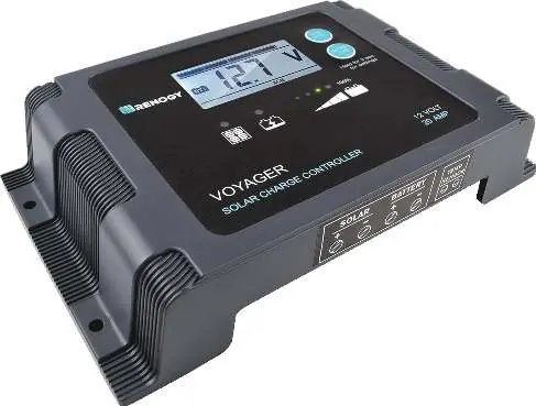
The Renogy Voyager 20A is a waterproof PWM charge controller designed for 12V solar systems. Crucial: Always connect the battery to the controller first before connecting the solar panels. Failure to do so may cause a dangerous high open-circuit voltage at the terminals.
General Information
The Voyager features 5-stage PWM charging (Soft-Start, Bulk, Absorption, Float, and Equalization) and is compatible with 7 battery types: Lithium-ion, LiFePO4, LTO, Gel, AGM, Flooded, and Calcium. It includes a backlit LCD and an LED bar for monitoring charge state and system information.
Installation
The controller is designed for vertical wall mounting. Ensure the location is protected from direct sunlight, high temperatures, and water. Maintain at least 6 inches (150mm) of clearance above and below the unit for ventilation.
Wiring
The controller has clearly labeled terminals for solar and battery. Use appropriate wire gauges based on the distance between the controller and the battery. Ensure all connections are tight but do not over-torque the screw terminals.
Operation
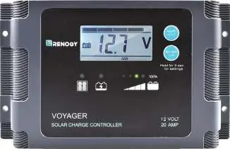
Upon power-up, the controller performs a self-test. Use the AMP/VOLT button to cycle through display parameters: Battery Voltage, Charging Current, Charged Capacity, and Battery Temperature (if a sensor is connected).
Selecting Battery Type
To select the battery type, press and hold the BATTERY TYPE button for 3 seconds to enter selection mode. Press the button repeatedly until the desired battery type is displayed. The selection will be saved automatically after a few seconds.
Troubleshooting
The controller uses an LED error code system to diagnose faults. If an error occurs, the screen will flash an error code (e.g., b01, b02, b03, b04, PO1, PO2, otP). Refer to the LED Error Behavior section in the manual to identify the specific fault, such as battery over-voltage, reverse polarity, or over-temperature.
Maintenance
Periodically check wiring for damage or wear. Tighten all terminals and inspect for loose, broken, or burnt connections. Clean the case occasionally with a damp cloth.
Practical help
Common problems
Controller does not charge during the day
Confirm tight connections from battery and solar panels. Check for reversed polarity on solar terminals. Check for error codes on the display.
Battery over voltage
Disconnect the battery and use a multi-meter to check the battery voltage. Ensure it does not exceed the controller's rated specifications.
Before use
- Ensure the battery is connected to the controller before the solar panels.
- Verify the battery type is correctly set (Lithium-ion, LiFePO4, LTO, Gel, AGM, Flooded, or Calcium).
- Ensure input voltage does not exceed 25 VDC.
- Check for 6 inches (150mm) of clearance for ventilation.
- Ensure all wire connections are tight.
Specs in practice
- Rated Charging Current
- 20A
- Maximum Solar Voltage (OCV)
- 26V
- Ingress Protection
- IP65 (Waterproof)
- Normal Battery Voltage
- 12V
Images and diagrams
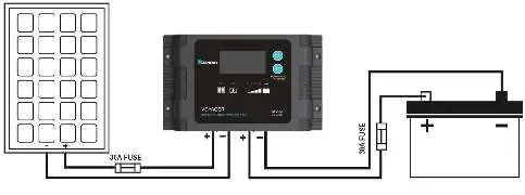
- The wiring diagram illustrates the solar panel connected to the solar terminals and the battery connected to the battery terminals, with fuses installed on both positive lines.
Model compatibility
- Compatible with 12V solar systems.
- Supports 7 battery types: Lithium-ion, LiFePO4, LTO, Gel, AGM, Flooded, and Calcium.

Manual page author
David Miller
Documentation analyst
Organizes user manual content into clear summaries, with attention to model details, product context, and everyday usability.