Lighting / Fixtures
Installation Manual for Lucci Decor Desi LED Step Light
A comprehensive installation and safety guide for the Lucci Decor Desi LED Step Light. This manual covers wiring instructions, mounting procedures, technical specifications, and maintenance requirements for both square and round fascia...
Quick answers from the manual
Quick answer
- The Lucci Decor Desi LED Step Light must be installed by a licensed electrician. It is an IP44-rated fixture, not compatible with dimmer switches, requiring a 70mm cutout. p. 1, 2
Key actions
- Connect mains supply wire to the LED input wire terminals (Neutral: Blue/Black to N; Live: Brown/Red to L). p. 2
- Cut a 70mm hole in the installation location. p. 1, 2
First start
- Ensure power is OFF, prepare the cutout, wire the terminal block according to polarity, and push the fitting into the wall using the side clips. p. 1, 2
Show 3 more answers Show less
Maintenance and reset
- Clean by wiping with a damp clean cloth. Never soak the fitting with water. Ensure power is OFF and the fitting has cooled down before maintenance. p. 2
Technical specifications
| Parameter | Value | Meaning | Pages |
|---|---|---|---|
| Rated Voltage | 220-240V~ 50Hz | Standard mains power requirement. | p. 1, 2 |
| Rated Wattage | 1W | Power consumption. | p. 2 |
| IP Rating | IP44 | Ingress protection rating. | p. 1, 2 |
| Cut Out Size | Ø 70mm | Required hole diameter for installation. | p. 2 |
Where to find it in the PDF
- Installation Instructions p. 1, 2
- Installation Diagrams p. 3
Table of contents
Quick guide from the manual
The Lucci Decor Desi LED Step Light is an IP44-rated fixture suitable for indoor or outdoor use. Installation must be performed by a licensed electrician in accordance with local and national wiring rules. This fitting is not compatible with dimmer switches; using one will void the warranty.
Installation requirements
- Electrical: Must be installed by a licensed electrician. Ensure power is switched OFF before starting.
- Location: Suitable for wall mounting near ground level for pathway lighting. Avoid areas near air vents or permanent damp/moist locations.
- Compatibility: Not suitable for use with dimmer switches.
- Preparation: Check the wall type for mounting depth and thickness. Ensure there is sufficient clearance for cooling and no thermal insulation or combustible materials near the fitting.
Installation steps
- Switch power OFF to the circuit.
- Remove all packaging material.
- Check the wall type and ensure the cutout size is correct (Ø 70mm).
- Remove the LED light fitting from the plastic canister.
- Determine if the plastic canister is required for your wall type (e.g., concrete or rendered walls).
- Cut the hole in the installation location.
- Remove the cover from the terminal box and connect the mains supply wire to the LED input wire terminals.
- Push all wiring into the cutout hole and position the fitting into the hole while pushing the side clips/springs in until flush against the wall.
- Return electrical power to the circuit.
Wiring instructions
Ensure the correct supply input wires are inserted into the right polarity marking on the terminal block. Incorrect electrical wiring will void the warranty.
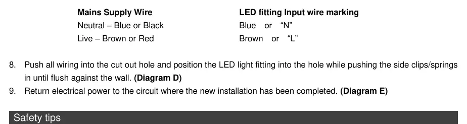
- Neutral: Connect to Blue or Black wire (marked "N").
- Live: Connect to Brown or Red wire (marked "L").
Safety and maintenance
- Safety: Always ensure the power is OFF and the fitting has cooled down before performing any maintenance, cleaning, or adjustment.
- Cleaning: Wipe with a damp clean cloth. Never soak the fitting with water.
- Hazards: Ensure the fitting does not come in contact with corrosive chemicals.
Technical specifications
- Rated Voltage: 220-240V~ 50Hz
- Rated Wattage: 1W total
- LED Details: SMD-LED, 4000K
- IP Rating: IP44
- Cut Out Size: Ø 70mm
- Weight: 0.14kg (Square), 0.13kg (Round)
- Dimensions: 80mm x 80mm (Square), 80mm diameter (Round); 53mm extension
Practical help
Common problems
Dimmer switch usage
This fitting is not suitable for use with dimmer switches. Using one will void the warranty.
Missing components
Lay out all components on a smooth surface before assembling. If parts are missing, return the complete product to the place of purchase.
Damaged fitting
Do not operate or install any product that appears damaged. Return it to the place of purchase for inspection, repair, or replacement.
Before use
- Ensure a licensed electrician is available for installation.
- Verify the wall type and ensure sufficient clearance for cooling.
- Check that no thermal insulation or combustible materials are near the fitting.
- Confirm the power to the circuit is switched OFF.
- Verify the cutout size is Ø 70mm.
Show more Show less
Images and diagrams
- Diagram A: Power isolation.
- Diagram B: Cutting the installation hole.
- Diagram C: Wiring connection to the terminal block.
- Diagram D: Inserting the fitting into the wall using side clips.
- Diagram E: Restoring power.
Model compatibility
- Not compatible with dimmer switches.
- Suitable for indoor or outdoor use (IP44).
- Requires specific cutout size of 70mm.

Manual page author
David Miller
Documentation analyst