Automotive / Car Audio
AudioControl The Epicenter InDash Bass Processor User Manual
Comprehensive user guide for the AudioControl The Epicenter InDash bass restoration processor. Includes installation instructions, wiring diagrams, front panel control explanations, and troubleshooting tips.
Table of contents
Manual images
Click an image to enlargeQuick Guide from the Manual
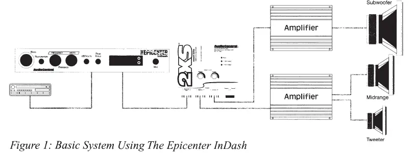
The AudioControl The Epicenter InDash is a bass restoration processor designed to be installed in the signal path between a source unit and an external amplifier. It must be installed BEFORE any crossover. Key precautions include turning down bass tone controls on your system before initial use and ensuring you have appropriate speakers and amplification to handle the restored bass frequencies.
Product Overview
The Epicenter InDash features a unique bass restoration circuit that recreates low-frequency information lost during recording. It includes an SPL display (up to 160 dB), battery voltage monitoring, speaker-level inputs, and Para-BASS equalization controls to shape the enhanced bass.
Front Panel Controls
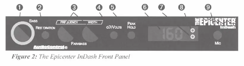
- Bass Restoration Control (The Knob): Adjusts the amount of processed bass added to the signal. Listen first, then increase.
- Restoration Switch: Engages the bass restoration circuit.
- Para-BASS Controls: Frequency knob selects the center frequency (27Hz-63Hz); Width knob adjusts the range around that frequency.
- dB/Volts Switch: Toggles the display between SPL levels (dB) and electrical levels (volts).
- Peak Hold: Displays the highest measured SPL or voltage reading.
- Indicators: Includes a Bass Restoration Indicator and a High SPL Warning Indicator (activates at 120 dB).
Installation and Wiring
Placement: Mount the unit on or near the dashboard, ensuring it is accessible from the driver's seat. Avoid hot spots like the firewall or engine compartment.
Power Wiring: Disconnect the negative battery terminal before starting. Use 18 gauge or larger wire for power and ground. Connect the remote turn-on wire to the source unit's remote output. The illumination wire can be connected to a switched 12-volt source or the dash light dimmer.
Audio Wiring: Connect the main source unit to the Epicenter InDash inputs (RCA or speaker level). Connect the outputs to the next component in the signal chain (e.g., equalizer, crossover, or amplifier).
Adjusting Para-BASS
The Para-BASS system allows you to tune the bass response to your vehicle's acoustics. Use the Frequency control to target the specific bass range and the Width control to adjust the filter shape. A real-time analyzer or careful listening is recommended for optimal setup.
Troubleshooting
- No Power: Check power and remote turn-on wire connections; verify the fuse is not blown.
- No Bass Restoration: Turn the bass knob clockwise. Ensure the unit is installed before any crossovers in the signal chain.
- Distorted Sound: Decrease the amount of bass restoration by turning the knob counter-clockwise.
- No Display: Check power connections.
Specifications
- Maximum Input Level: 15 Vrms
- Maximum Output Level: 13.5 Vpeak
- Frequency Response: 10Hz-100kHz (+/- 1dB)
- Total Harmonic Distortion: 0.003%
- Signal to Noise Ratio: -130dB
- High SPL Warning: 120 dB
- Input Impedance: 10 Kohms
- Power Draw: 300mA
Practical help
Common problems
No Power
Check that the power wire and remote turn-on wires are connected and that the fuse has not blown.
No Bass Restoration
Turn the bass knob clockwise. Ensure the unit is installed in the signal path BEFORE any crossovers.
Distorted Sound
Decrease the amount of bass restoration by turning the dash control knob counter-clockwise.
No Display
Check power connections; if the unit has power but no display, refer to the 'No Power' troubleshooting steps.
Before use
- Disconnect the negative battery terminal before working on electrical connections.
- Install the unit in the signal path between the source unit and external amplifier.
- Ensure the unit is installed BEFORE any crossover circuit.
- Use 18 gauge or larger wire for power and ground connections.
- Ensure the system is turned OFF before moving any internal jumpers.
- Register your product at www.audiocontrolregistration.com for warranty validation.
Specs in practice
- Maximum Input Level
- 15 Vrms; the highest signal voltage the unit can accept without clipping.
- Frequency Response
- 10Hz-100kHz; the range of frequencies the unit can process.
- Total Harmonic Distortion
- 0.003%; indicates very high signal purity and low distortion.
- High SPL Warning
- 120 dB; the threshold at which the unit provides a visual warning to protect hearing.
Images and diagrams
- Front Panel: Shows the main control knob, Para-BASS adjustments, and display toggles.
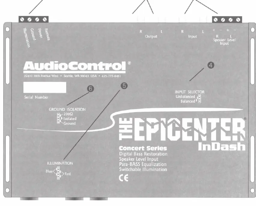
- Top View: Illustrates the location of power, input, and output connectors, as well as internal jumpers for grounding and illumination.
- Wiring Diagrams: Demonstrate how to connect the processor with various system configurations, including EQs and factory source units.
Model compatibility
- Compatible with most factory-installed source units, including Bose systems.
- Must be installed before any crossover in the signal chain.
- Input Grounding can be switched between Balanced (default) and Unbalanced if ground loops occur.

Manual page author
Emily Carter
User documentation editor
Prepares concise manual descriptions and highlights the most useful setup, operation, and maintenance information for readers.