Automotive / Car Audio
User Guide for AudioControl Epicenter Micro Bass Restoration Processor
Comprehensive user guide for the AudioControl Epicenter Micro. Learn how to install, wire, and tune your bass restoration processor for optimal sound quality.
Table of contents
Manual images
Click an image to enlargeQuick Guide from the Manual
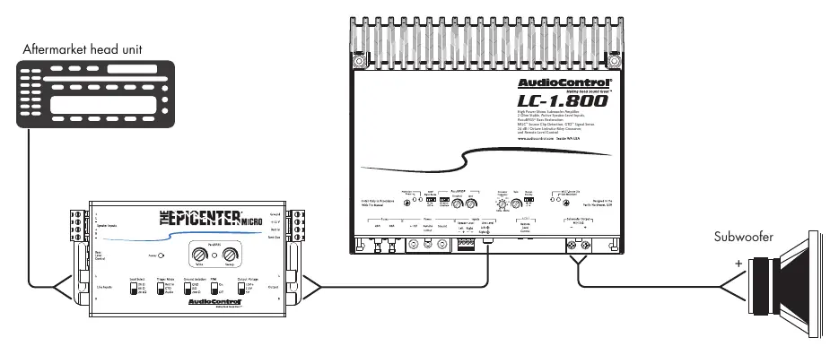
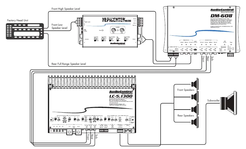
The AudioControl Epicenter Micro is a bass restoration and enhancement processor designed to improve low-frequency response in car audio systems. It is intended to be installed in the signal path between the source unit and the amplifier, ideally before any crossover or signal processor. Proper installation and tuning are essential for achieving the best bass performance without damaging your speakers.
Installation and Wiring
Before beginning installation, ensure the negative battery terminal is disconnected to prevent electrical shorts. Use 14 to 18 AWG insulated wiring for power and ground connections.
Placement and Mounting
- Placement: Install the unit in the signal path after the source and before any crossover circuit.
- Mounting: Select a permanent location, mark the holes, drill pilot holes, and secure the chassis using self-tapping screws. Ensure you are not drilling into fuel lines or existing wiring.
Power Connections
- Ground: Connect to the negative battery terminal, a ground bus, or a verified ground location. Do not use the factory head unit ground.
- Positive (+12V): Connect to a constant 12V source (battery recommended), fused at 1 amp.
- Remote In: Connect to the head unit's remote turn-on or switched 12V source.
- Remote Out: Connect to the amplifier's remote or 12V trigger input.
ACR-4 Dash Control Installation
The ACR-4 remote allows for level control of the bass restoration effect and overall sub volume.
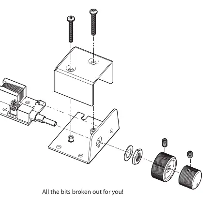
- Bracket Mount: Mount under the dashboard using the provided bracket and four screws.
- Custom Flush Mount: Remove the knobs and enclosure. Drill a 9/32" hole for the potentiometer, a 1/8" hole for the lock tab, and a 1/8" hole for the LED. Reassemble the components on the dashboard.
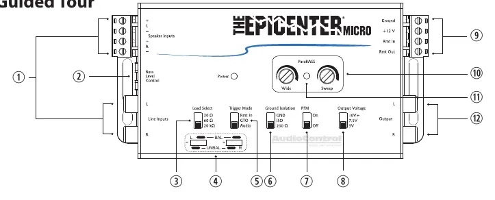
Adjusting ParaBASS Controls
ParaBASS allows you to shape the bass restoration effect to your vehicle's acoustics.
- Sweep: Selects the center frequency (the frequency most affected) between 27 Hz and 63 Hz.
- Wide: Controls the shape of the filter centered around the Sweep frequency.
Output and Subsonic Filter Settings
- Bass Output Control: Adjust the voltage output settings (5V, 7.5V, 10V) to match your amplifier's input voltage rating and speaker size. Listen to the factory setting before making changes.
- PFM Subsonic Filter: A 20Hz filter that protects speakers from ultra-low frequencies. It can be bypassed if necessary, but use caution as this may damage subwoofers.
Troubleshooting
- No Power: Check the "Power" light on the chassis. If off, verify power and remote turn-on wire connections and check the fuse. If the remote LED is off but the chassis light is on, check the remote cable connection.
- No Restoration: Ensure the unit is installed before any crossovers. Check that the ACR-4 cable is fully plugged in. Try turning the outer knob clockwise.
- Distorted Sound: Decrease the bass restoration effect by turning the knobs counter-clockwise. Re-engage the PFM filter or lower the Voltage Output setting.
Practical help
Common problems
No power to the unit
Check the 'Power' light on the chassis. If off, verify power and remote turn-on wire connections and check the fuse. If the remote LED is off but the chassis light is on, check the remote cable connection.
No bass restoration effect
Ensure the unit is installed before any crossovers in the signal chain. Check that the ACR-4 cable is fully plugged in and try turning the outer knob clockwise.
Distorted sound or excessive speaker movement
Decrease the bass restoration effect by turning the knobs counter-clockwise. Re-engage the PFM filter or lower the Voltage Output setting.
Before use
- Turn down bass frequencies on any existing equalizer to zero boost.
- Reduce loudness or secondary bass controls before turning on the unit.
- Ensure the unit is installed before any crossover in the signal path.
- Use 14-18 AWG wire for power and ground connections.
- Disconnect the negative battery terminal before starting installation.
Specs in practice
- Maximum Input Line Level (RCA)
- 15Vrms
- Max Output Level
- 13V Peak
- Frequency Response
- 10Hz to 22kHz (+/- 1dB)
- Current Draw
- 300mA
Images and diagrams
- Wiring diagram shows connection from head unit to Epicenter Micro, then to amplifier and subwoofer.
- ACR-4 installation diagram details mounting bracket and flush mount options.
Model compatibility
- Compatible with factory and aftermarket systems.
- Load Selection (20Ω, 60Ω, 20kΩ) helps integrate with various factory amplifiers.

Manual page author
Michael Turner
Technical manual editor
Reviews PDF manuals for structure, safety notes, and practical product details so readers can find the right information quickly.