Home Appliances / Commercial Kitchen Equipment
User Manual for Avantco 177HWDD2 Hot Water Dispenser
Quick guide for the Avantco 177HWDD2 Hot Water Dispenser. Includes installation steps, panel operation, temperature settings, cleaning instructions, and technical specifications.
Quick answers from the manual
Quick answer
- The Avantco 177HWDD2 is a hot water dispenser. To operate, connect the water line, plug it into a 110-120V outlet, and use the control panel to set the temperature. Perform deliming every 6 months. p. 1, 2, 4, 5
Key actions
- Turn on/off p. 3, 4
- Adjust temperature p. 4
- Delime unit p. 5
First start
- Connect water line and plug in unit. p. 2, 4
- Press On/Off button. p. 4
Problems and fixes
Water Low indicator is on
Water supply is not sufficient or water inside does not reach the minimum level.
p. 3Error codes
| Code | Meaning | Action | Pages |
|---|---|---|---|
| ELL | Water level is too low. | Check water supply. | p. 3 |
Technical specifications
| Parameter | Value | Meaning | Pages |
|---|---|---|---|
| Voltage | 110-120 V | Operating voltage | p. 5 |
| Wattage | 1800W | Power consumption | p. 5 |
| Capacity | 2 Gallons | Water storage capacity | p. 5 |
Where to find it in the PDF
- Installation p. 2
- Panel Operation p. 3
- Cleaning and Maintenance p. 5
Table of contents
Manual images
Click an image to enlargeQuick guide from the manual
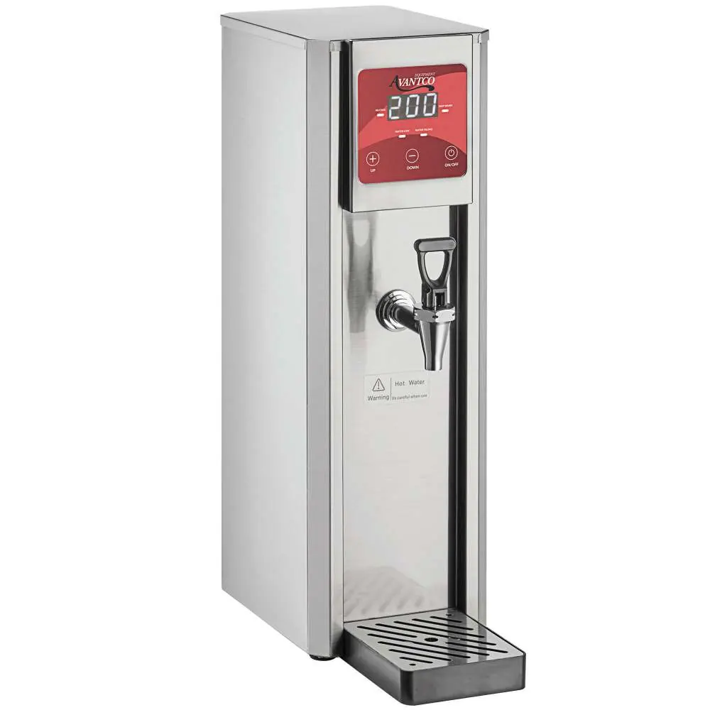
This guide covers the installation, operation, and maintenance of the Avantco 177HWDD2 Hot Water Dispenser. Ensure the unit is placed on a stable surface and connected to a 110-120V outlet before use.
Installation
Follow these steps to install the dispenser:
- Place the dispenser on a solid, level table.
- Position the water tray at the bottom in front of the unit.
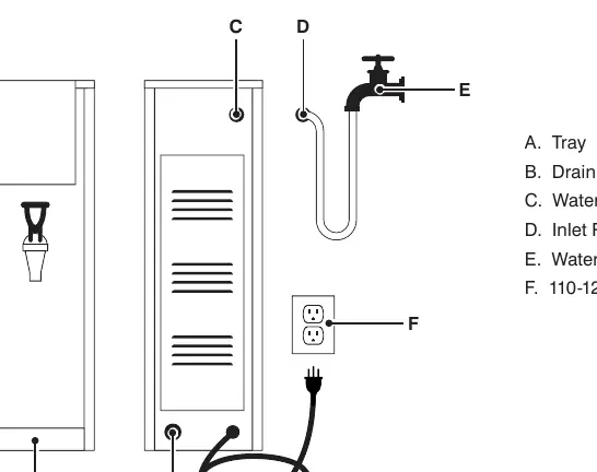
- Connect one end of the inlet pipe to the water inlet on the back of the unit.
- Connect the other end of the inlet pipe to your water supply or faucet.
- Turn on the water switch.
- Plug the power cord into a 110-120V socket.
Panel Operation
The control panel allows you to manage the dispenser:
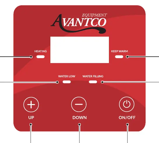
- On/Off: Hold for 3 seconds to turn off; press lightly to turn on.
- Up/Down Buttons: Used to adjust the temperature.
- Heating Indicator (A): Indicates the machine is heating.
- Keep Warm Indicator (F): Indicates the water has reached the set temperature.
- Water Low Indicator (B): Indicates insufficient water or level below minimum (Display code: ELL).
- Water Filling Indicator (G): Indicates the machine is replenishing water.
Normal Operation
Upon first use, plug in the unit and press the On/Off button. The machine will automatically heat and boil water until the Keep Warm indicator turns on. To set the temperature, press and hold the Down button for 3 seconds; the screen will display the current setting. Use the Up or Down buttons to adjust the temperature (factory default is 210°F).
Daily Cleaning and Maintenance
Delime the unit every 6 months for best performance:
- Mix 10 oz. of fresh or condensed lemon juice with 32 oz. of water.
- Connect an external bottle water pump to the solenoid valve.
- Pump the lemon juice mixture into the water tank by turning on the unit.
- Let stand for 10 minutes and repeat 2-3 times.
- Connect back to the water source, run clean water through the unit, turn off the power, and wait for the boiler to cool.
- Empty all liquid from the unit.
Manufacturer information
Avantco Equipment
Practical help
Common problems
Water Low indicator (B) is on
The water supply is insufficient or the water level is below the minimum. Check water connection.
Unit not heating
Ensure the unit is plugged in and turned on. Check if the Keep Warm indicator is on.
Before use
- Place on a solid, level, stable surface.
- Ensure water line is connected and not leaking.
- Verify power outlet is 110-120V.
- Ensure water tray is positioned correctly.
Specs in practice
- Water input pressure
- 10-58 psi operating range.
Images and diagrams
- The installation diagram shows the connection of the inlet pipe (D) to the water inlet (C) and the water faucet (E).
- The control panel diagram identifies the Heating (A), Keep Warm (F), Water Low (B), and Water Filling (G) indicators.
Model compatibility
- Requires 110-120V power supply.
- Water input pressure must be between 10-58 psi.
- Requires 1/4 inch water connection.

Manual page author
Michael Turner
Technical manual editor
Reviews PDF manuals for structure, safety notes, and practical product details so readers can find the right information quickly.