Electronics / Security Cameras
Installation Guide for Avigilon H4 IR PTZ Camera
Quick installation and setup guide for the Avigilon H4 IR PTZ Camera. Includes mounting instructions, wiring diagrams, power requirements, and troubleshooting steps.
Table of contents
Manual images
Click an image to enlargeQuick guide from the manual
This guide provides essential installation and setup instructions for the Avigilon H4 IR PTZ Camera. Before installation, ensure you have the necessary tools and a compatible power source. The camera requires a UL Listed Power Unit (Class 2, LPS, or Limited Power Source) rated 24VAC or 24VDC, or a 95W PoE injector. For cold environments (-10°C to -40°C), a 95W PoE or auxiliary power supply is mandatory to allow for a warm-up period.
Overview
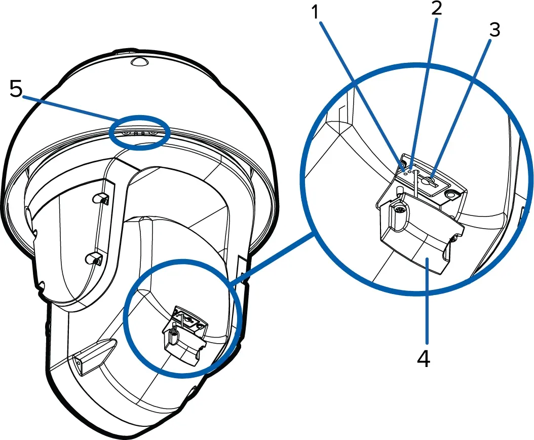
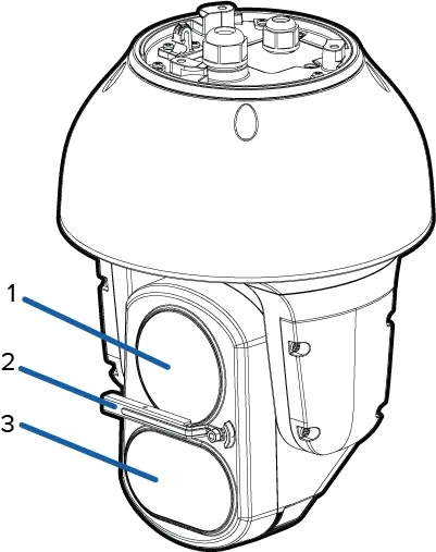
The camera features a rear panel with a Link LED, Connection Status LED, microSD card slot, and a sprayer mounting location (on -WP models). The top view includes a lanyard anchor, Ethernet port, and power/IO cable access. The front view houses the lens, wiper (on -WP models), and variable IR illuminators.
Installation
The camera can be mounted using a pendant wall mount or an NPT mount. Both mounts are sold separately.
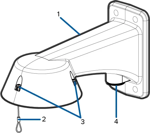
Installing the Pendant Wall Mount
- Determine cable entry: use the rear hole for surface entry or the 3/4 inch NPT hole for conduit.
- Use the provided template to drill mounting holes.
- Pull cables through the mount.
- Fasten the mount to the surface.
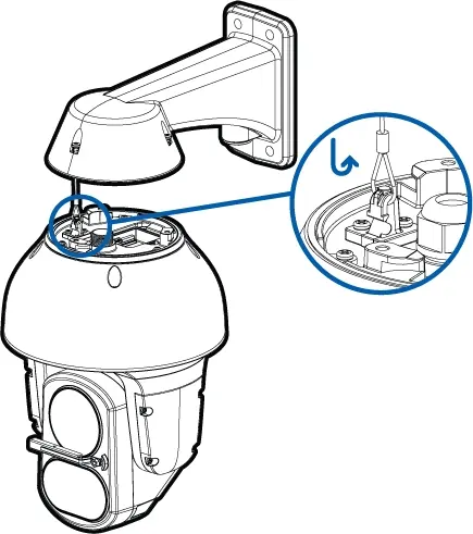
- Connect the safety lanyard from the mount to the camera base.
Installing the NPT Mount
- Pull the cable through the NPT conduit pipe.
- Attach the 1-1/2 inch NPT-female to NPT-female adapter to the pipe using thread seal tape.
- Secure the lock nut and NPT adapter.
- Connect the safety lanyard to the camera.
Connecting Cables
The camera supports Ethernet (PoE) or external power. To connect:
- Remove sealing gland caps.
- Connect external I/O devices to the I/O harness if needed.
- Connect power via PoE injector or auxiliary 24V DC/AC power wires.
- Thread the Ethernet cable through the gland, crimp the connector, and tighten the gland to ensure a weather-tight seal.
Configuration
After physical installation, access the camera via a web browser using its IP address. Cameras manufactured after January 1, 2020, require the creation of an administrator user upon first login. You can also use the Avigilon Camera Configuration Tool or Avigilon Control Center (ACC) to initialize the camera.
Troubleshooting
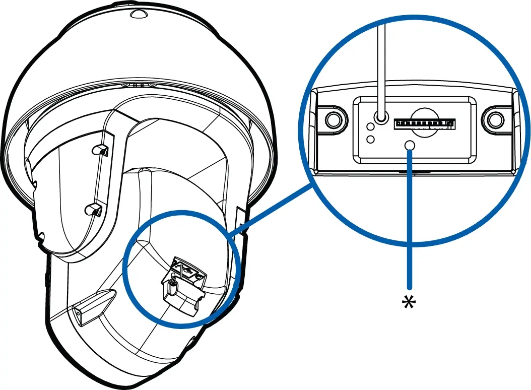
If the camera does not display video after power-up in cold environments, it may be in a cold start delay mode, which can take up to 60 minutes to warm up. For network issues, check the LED indicators. If the green LED is off and the amber LED is on, perform a factory reset using the physical firmware revert button located under the SD card cover.
Cleaning
Use a microfiber cloth to clean the dome bubble. For the lens and IR window, activate the washer/wiper via the web interface or ACC software. If manual cleaning is required, use hand soap or non-abrasive detergent.
Practical help
Common problems
Video does not display after power up
If in a cold environment (-10°C to -40°C), the camera may be in a cold start delay. Wait up to 60 minutes for it to warm up.
Green LED is off and amber is on
Perform a factory reset using the physical firmware revert button. Resetting via the web interface will not resolve this.
Camera cannot obtain an IP address
Check if the device is connected to a DHCP server. If not, it will use Zero Configuration Networking (Zeroconf) in the 169.254.0.0/16 subnet.
Before use
- Ensure power source is UL Listed (Class 2, LPS, or Limited Power Source).
- Verify the mounting surface can support the camera weight.
- Ensure the safety lanyard is securely connected during installation.
- Check that the Ethernet cable is CAT5.
- Verify the microSD card (if used) is class 6 or better.
Specs in practice
- Power Consumption
- 75W max; 105VA with 24V AC power.
- Operating Temperature
- -40°C to +60°C (-40°F to 140°F) with external power or 95W PoE.
- Impact Rating
- IK10 (camera body only).
- Weather Rating
- IEC 60529 IP66.
Images and diagrams
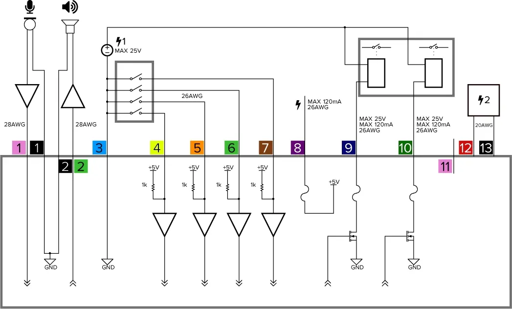
- Wiring diagram illustrates connections for audio input/output, digital inputs (Relay 1-4), and power supply.
- Mounting diagrams show the correct sequence for attaching the camera to wall and NPT mounts.
Model compatibility
- Requires 95W PoE or auxiliary power for cold environments.
- Compatible with Avigilon Control Center (ACC) software.
- Supports ONVIF Profile S.

Manual page author
Michael Turner
Technical manual editor
Reviews PDF manuals for structure, safety notes, and practical product details so readers can find the right information quickly.