Electronics / Security Cameras
User Manual for Speco Technologies 08VT2 Network Camera
Quick start guide for the Speco Technologies 08VT2 network camera. Includes installation steps, wiring instructions, network configuration, and maintenance tips.
Table of contents
Manual images
Click an image to enlargeQuick guide from the manual
The Speco Technologies 08VT2 is a network camera designed for professional installation. Key operational requirements include:
- Power: Use a certified 12VDC Class 2 power supply or a PoE switch/injector. Do not connect both power sources simultaneously.
- Default Login: The default username is admin and the default password is 1234.
- Network: The camera is set to DHCP by default. Use the IP Scanner software to locate the device on your network.
- Installation: Ensure the mounting surface can support three times the weight of the camera and junction box.
Safety and Maintenance
Follow these guidelines to ensure device longevity and safety:
- Electrical Safety: Installation must conform to local electrical codes. Grounding the camera is recommended to enhance reliability.
- Environment: Install in a cool, dry place away from direct sunlight, heat sources, and extreme temperatures. Avoid exposure to water or electromagnetic radiation.
- Cleaning: Shut down and unplug the device before maintenance. Use a blower to clean the lens surface. For the enclosure, use a dry soft cloth. For grease or fingerprints on the dome cover, use an oil-free cotton cloth or paper soaked with alcohol or detergent, wiping from the center outward.
Package Contents
Before installation, verify that the package contains the following items:
- Camera
- Quick start guide
- Tapping screws (x3)
- Plastic plugs (x3)
- CD
- Drill template
- Screwdriver
- Junction box
Device Overview
The camera features several connection points and components:
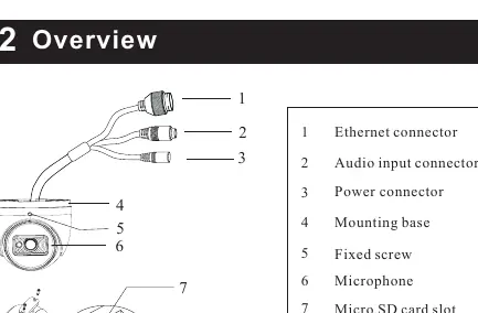
- Connectors: Ethernet connector, Audio input connector, and Power connector.
- Internal Components: Micro SD card slot and Reset button (accessible by removing the cover).
- Mounting: Includes a mounting base and fixed screw for angle adjustment.
Installation
- Junction Box: Open the mounting base and upper cover. Install the junction box onto the wall using the provided screws.
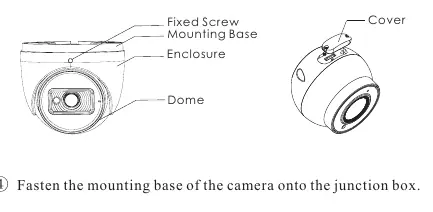
- SD Card: Loosen the fixed screw to disassemble the camera. Remove the cover from the dome to insert the SD card. Reinstall the cover firmly.
- Mounting: Fasten the mounting base of the camera onto the junction box.
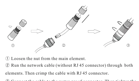
- Wiring: Route cables through the cable hole. For outdoor installations, use the provided water-proof connector.
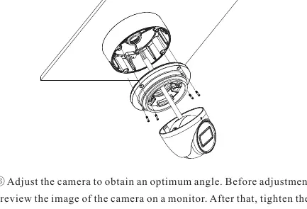
- Final Adjustment: Reinstall the upper cover, mount the dome, and adjust the camera angle. Preview the image on a monitor before tightening the fixed screw.
Network Operation
To access the camera via a web browser:
- Ensure the camera and PC are on the same local network.
- Install and run the IP Scanner from the provided CD or download it from the Speco Technologies website.
- Locate the device in the list to view its IP address.
- Double-click the device in the list or enter the IP address directly into your web browser.
- Log in using the default credentials (admin/1234) and install any required plugins.
Practical help
Common problems
Camera does not power on
Ensure you are using a certified 12VDC Class 2 power supply or a PoE switch. Do not connect both power sources at the same time.
Dirt or grease on the lens/dome
Use a blower for dust. For grease or fingerprints, use an oil-free cotton cloth with alcohol or detergent, wiping from the center outward.
Cannot find camera on network
Ensure the camera and PC are connected to the same local network. Use the IP Scanner software to identify the camera's IP address.
Before use
- Verify the wall or ceiling can support three times the weight of the camera and junction box.
- Ensure you have a 12VDC Class 2 power supply or a PoE switch/injector.
- Check that all package components are present.
- Install the IP Scanner software on your PC.
- Ensure the installation environment is cool, dry, and free from extreme temperatures.
Specs in practice
- 12VDC Class 2
- Required power input specification for non-PoE installations.
Images and diagrams
- The wiring diagram illustrates the connection of the Ethernet, audio, and power cables, including the use of the water-proof connector.
- The installation diagrams show the step-by-step process of mounting the junction box and attaching the camera base.
Model compatibility
- Outdoor installations require the use of the included water-proof connector.
- Installation and repair should be performed by qualified personnel only.

Manual page author
Michael Turner
Technical manual editor
Reviews PDF manuals for structure, safety notes, and practical product details so readers can find the right information quickly.