Electronics / Security Cameras
Quick Start Guide for Speco Technologies 05D2 Network Camera
Get started with your Speco Technologies 05D2 network camera. This guide covers installation, wiring, web interface login, and maintenance instructions.
Table of contents
Manual images
Click an image to enlargeQuick Start Guide Overview
This guide provides essential instructions for installing and configuring the Speco Technologies 05D2 network camera. Ensure all components are present before beginning installation. The camera is designed for professional installation only.
Package Contents
Verify that your package includes the following items:
- Camera
- Quick start guide
- 4 tapping screws
- CD
- Drill template
- 4 plastic plugs
- Rubber plug
- Junction box
- Screwdriver
Device Overview
The camera features several connectors and components:
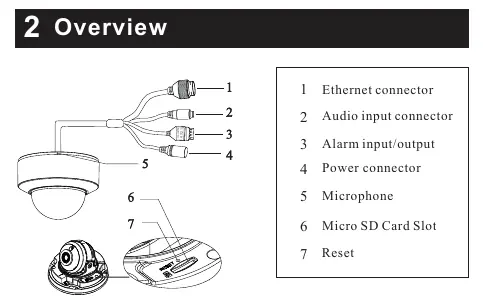
- 1: Ethernet connector
- 2: Audio input connector
- 3: Alarm input/output
- 4: Power connector
- 5: Microphone
- 6: Micro SD Card Slot
- 7: Reset button
Installation
Before starting, ensure the mounting surface (wall or ceiling) can support three times the weight of the camera.
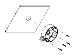
- Install the junction box onto the wall using the provided screws.
- Rotate the trim ring anticlockwise to remove it from the camera.
- Loosen the screws to open the lower dome.
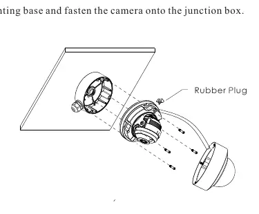
- Connect the cables, mount the rubber plug to the gap of the mounting base, and fasten the camera onto the junction box.
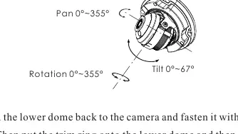
- Perform the three-axis adjustment by viewing the camera image on a monitor to achieve the optimum angle.
- Reinstall the lower dome, fasten with screws, and rotate the trim ring clockwise until locked.
Wiring and Connections
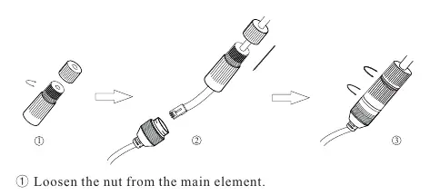
Network Cable: Loosen the nut from the main element, run the network cable (without RJ45 connector) through both elements, crimp the cable with an RJ45 connector, connect to the hermetic connector, and tighten the nut.
Power: Use a certified 12VDC Class 2 power supply. A PoE switch or injector can be used to power the camera, eliminating the need for a separate 12VDC supply. It is recommended to install the security cap for outdoor installations.
Web Operation and Login
The camera is set to DHCP by default. Use the IP Scanner tool (available on the included CD or via the Speco website) to locate the device on your local network. Once located, double-click the device in the list to open the web viewer or enter the IP address directly into a browser.
Default Credentials:
- Username: admin
- Password: 1234
Maintenance and Cleaning
Always shut down the device and unplug the power cable before maintenance. Do not touch the CMOS sensor. Use a blower to clean dust from the lens. For the enclosure, use professional optical cleaning methods; improper cleaning can affect IR functionality. If the dome cover is stained, use an oil-free soft brush or a cloth dampened with alcohol/detergent to wipe from the center outward.
Practical help
Common problems
Camera not found on network
Ensure the camera and PC are connected to the same local network. Use the IP Scanner tool to locate the device.
Poor IR functionality
Ensure the enclosure is cleaned using professional optical methods. Improper cleaning with standard cloth can cause IR reflection.
Device damage
Do not connect two power sources (e.g., 12VDC and PoE) to the device at the same time.
Before use
- Verify all package components are present.
- Ensure the mounting surface can support 3x the camera weight.
- Use a certified 12VDC Class 2 power supply.
- Install the security cap for outdoor installations.
- Ensure the camera and PC are on the same local network.
Specs in practice
- Pan/Tilt/Rotation
- Adjustable ranges for camera positioning (0-355 degrees for Pan/Rotation, 0-67 degrees for Tilt).
Images and diagrams
- The wiring diagram illustrates connections for Ethernet, Audio, Alarm, and Power.
- The installation diagram details the junction box mounting and dome assembly process.
Model compatibility
- PoE switch or injector can replace the need for a 12VDC power supply.

Manual page author
David Miller
Documentation analyst
Organizes user manual content into clear summaries, with attention to model details, product context, and everyday usability.