Tools / Power Tools
Owner's Manual for Bauer 56367 6-Inch Dual Action Polisher
Comprehensive user guide for the Bauer 56367 6-inch dual action polisher. Includes setup, operation, maintenance, troubleshooting, and safety instructions.
Quick answers from the manual
Quick answer
- The Bauer 56367 is a 6-inch dual action polisher. This manual covers safety, operation, maintenance, and troubleshooting. p. 1, 7
Key actions
- Replacing Backing Pad p. 12
First start
- Ensure trigger is off, plug in, set speed, test run for 30 seconds. p. 9
Problems and fixes
Tool will not start
Check cord, power, thermal reset, or internal damage.
p. 13Maintenance and reset
- If thermal reset breaker trips, turn off tool, allow to cool, and press reset button. p. 13
Technical specifications
| Parameter | Value | Meaning | Pages |
|---|---|---|---|
| Electrical Rating | 120VAC / 60Hz / 7.5A | Power requirements | p. 7 |
| No Load Speed | 2000-4600/min | Operating speed range | p. 7 |
Where to find it in the PDF
- Functions Diagram p. 7
- Assembly Diagram p. 15
Table of contents
Manual images
Click an image to enlargeQuick guide from the manual
This manual provides essential safety, operation, and maintenance instructions for the Bauer 56367 6-inch dual action polisher. Before using the tool, ensure the work area is clean, well-lit, and free of children or pets. Always wear appropriate personal protective equipment, including eye protection. The tool requires a 120VAC, 60Hz, 15A circuit. Always verify the trigger is in the off position before plugging the tool into a power source.
Functions
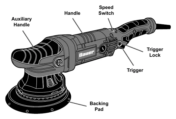
The polisher features an auxiliary handle for control, a speed switch to adjust RPM, a trigger with a lock for continuous operation, and a backing pad for attaching polishing accessories.
Operation
Workpiece Preparation: Ensure the surface is clean and free of dust, dirt, oil, and grease. Secure loose workpieces with clamps.
Waxing: Apply about two tablespoons of wax evenly onto the foam pad. Do not apply wax directly to the vehicle surface. Start the tool at the lowest speed to avoid throwing wax, then increase as needed. Keep the pad flat against the surface and use broad, sweeping strokes in a crisscross pattern.
Buffing: Once the wax has dried, replace the foam pad with a clean polishing bonnet. Secure the bonnet tightly. Start the tool and buff off the dried wax. Allow the tool to come to a complete stop before setting it down.
Maintenance
Cleaning: After each use, wipe external surfaces with a clean cloth. Periodically blow dust and grit out of the motor vents using dry compressed air while wearing safety goggles and a respirator.
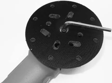
Replacing Backing Pad: To replace the backing pad, use a hex wrench to turn the spindle bolt counterclockwise. If necessary, access the spindle lock by removing the two screws and sliding the auxiliary handle off.
Troubleshooting
If the tool will not start, check the power connection, the outlet, and the thermal reset breaker. If the tool operates slowly, avoid forcing it and ensure the extension cord is of the correct gauge and length. If the tool overheats, check for blocked motor vents and ensure the extension cord is not causing a voltage drop.
Practical help
Common problems
Tool will not start
Check that the cord is plugged in, verify power at the outlet, check the thermal reset breaker, or have a technician inspect for internal damage.
Tool operates slowly
Do not force the tool. Ensure the extension cord is not too long or too thin (see manual for gauge requirements).
Overheating
Clear blocked motor housing vents and ensure the extension cord is not causing a voltage drop.
Before use
- Inspect for loose hardware.
- Check for damaged cord or electrical wiring.
- Ensure work area is clean and well-lit.
- Secure workpiece with clamps.
- Verify trigger is in the off position before plugging in.
Specs in practice
- Electrical Rating
- 120VAC / 60Hz / 7.5A
- No Load Speed
- 2000-4600/min
- Max Accessory Diameter
- 6 inches (150mm)
Images and diagrams
- The functions diagram identifies the trigger, trigger lock, speed switch, handle, auxiliary handle, and backing pad.
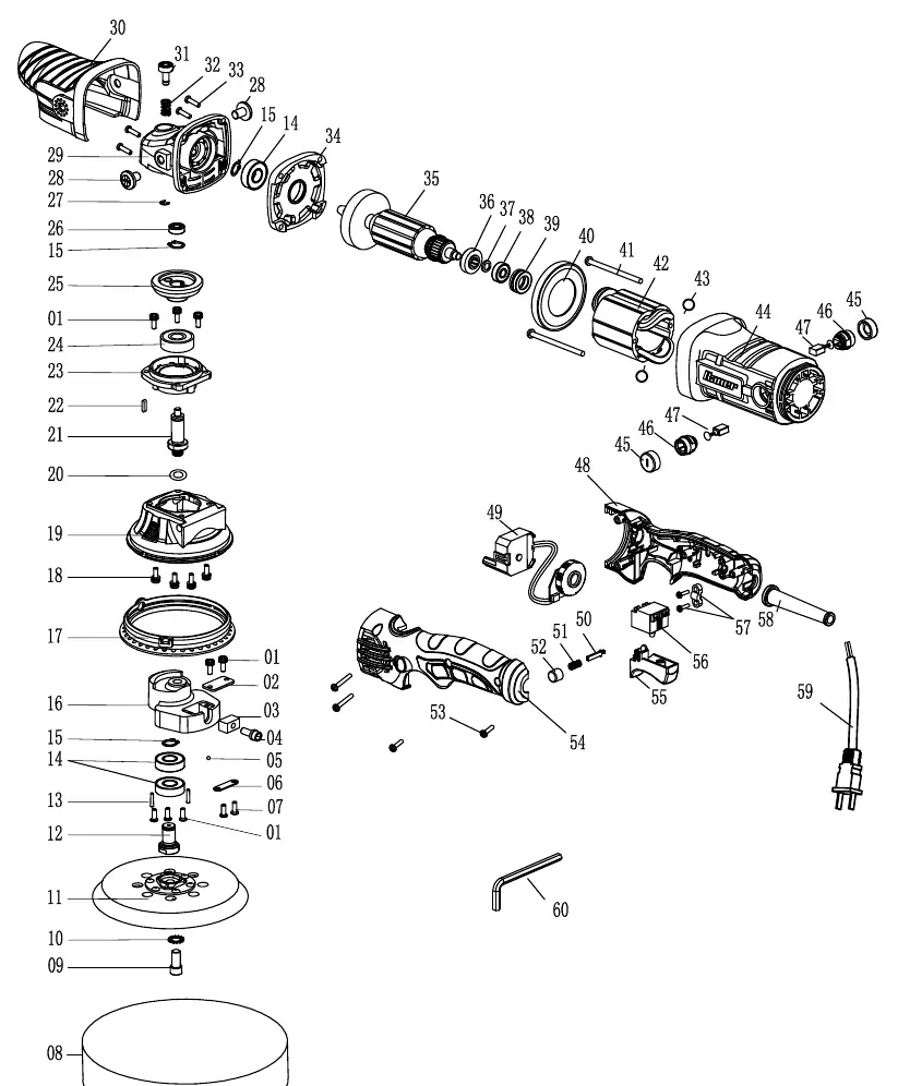
- The assembly diagram provides a detailed breakdown of internal components for maintenance and repair reference.
Model compatibility
- Requires 120VAC, 60Hz, 15A circuit.
- Use 6-inch polishing pads.

Manual page author
Michael Turner
Technical manual editor
Reviews PDF manuals for structure, safety notes, and practical product details so readers can find the right information quickly.