Tools / Power Tools
Owner's Manual for Bauer Wood Carving Disc
Quick guide for the Bauer Wood Carving Disc. Includes installation steps, safety precautions, assembly instructions, and maintenance tips for models 2061A-C35, 2061A-C414, and 2061A-C422.
Table of contents
Manual images
Click an image to enlargeQuick Guide
The Bauer Wood Carving Disc is designed for use with 4" or 4-1/2" angle grinders. Before use, ensure your grinder has a constant pressure switch (paddle or dead man switch) and a maximum speed of 14,000 RPM. Always use an auxiliary handle and wear appropriate personal protective equipment (PPE).
Safety Information
Warning: Improper use can lead to serious injury or death. Always maintain a firm grip on the tool with both hands. Never hold the workpiece in your hands or across your leg; secure it to a stable platform. Be aware of kickback risks, especially when working on corners or sharp edges. Do not use the disc to carve wood containing foreign objects like nails, screws, or rocks.
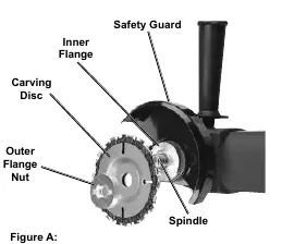
Installing the Carving Disc
1. Ensure the power tool is unplugged. 2. Press and hold the grinder's spindle lock. 3. Use a spanner wrench to remove the outer flange nut. 4. Place the Carving Disc onto the spindle, ensuring it is seated on the inner flange. 5. Thread the outer flange nut back on and tighten securely with the spanner wrench.
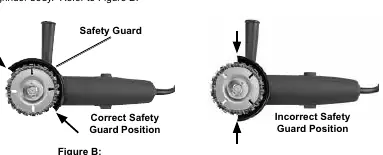
Adjusting the Safety Guard
The safety guard must be positioned correctly before use. 1. Lay the grinder on its side and loosen the guard hardware. 2. Rotate the guard until it is at an approximate 45° angle with the grinder body. 3. Tighten the hardware to secure the guard in place.
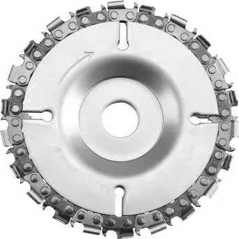
Disc and Chain Assembly
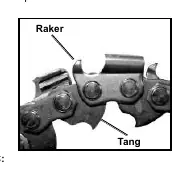
The disc consists of three components: a top disc (stamped TOP), a bottom disc (stamped BOTTOM), and a saw chain. 1. Place the bottom disc on a flat surface. 2. Arrange the saw chain around the outside edge, ensuring chain link tangs fit over the perimeter and rakers face left. 3. Place the top disc on the assembly, aligning the slots, and ensure the chain is secured between the two discs.
Operation
1. Ensure the switch is in the off-position before plugging in the tool. 2. Start the tool and allow it to reach full speed before touching the workpiece. 3. Use both hands to operate the grinder. 4. Cut by pulling the saw back towards you, not pushing away. 5. Do not apply excessive pressure; let the tool do the work. 6. After use, turn off the tool, allow it to come to a complete stop, and unplug it before setting it down.
Maintenance
Periodically sharpen the saw chain for optimum performance. 1. Remove the disc from the tool. 2. Use the center plug to hold the assembly together. 3. Sharpen the saw chain blades using a standard 1/8" or 5/32" chainsaw file.
Practical help
Common problems
Disc binds or kicks back
Ensure proper grip with both hands, use the auxiliary handle, do not force the tool into the workpiece, and check for foreign objects in the wood.
Chain not cutting effectively
Check chain direction. If installed backwards, it will not cut and may cause heat buildup/burning.
Tool bogs down during operation
Use lighter pressure and allow the tool to do the work.
Before use
- Ensure angle grinder has a constant pressure switch (paddle/dead man).
- Verify grinder speed is 14,000 RPM or less.
- Check that safety guard is properly positioned at 45°.
- Wear ANSI-approved safety goggles and heavy-duty gloves.
- Remove all foreign objects (nails, screws) from workpiece.
- Secure workpiece to a stable platform.
Specs in practice
- Spindle Size
- 5/8 inch - Required for mounting.
- Chain File Size
- 1/8" or 5/32" - Used for sharpening the chain.
Images and diagrams
- Figure A: Shows the order of components on the spindle (Inner Flange -> Carving Disc -> Outer Flange Nut).
- Figure B: Illustrates the correct 45° angle for the safety guard.
- Figure C: Shows the correct orientation of the saw chain rakers and tangs.
Model compatibility
- Compatible with 4" or 4-1/2" angle grinders.
- Requires grinder with constant pressure switch.
- Not for use on grinders requiring modification of the safety guard.

Manual page author
David Miller
Documentation analyst
Organizes user manual content into clear summaries, with attention to model details, product context, and everyday usability.