Tools / Power Tools
User Manual for Bauer 9 Inch Variable Speed Drywall Sander 21105E-B
Comprehensive user manual for the Bauer 9 Inch Variable Speed Drywall Sander (21105E-B). Includes detailed instructions for assembly, safe operation, maintenance, and troubleshooting.
Quick answers from the manual
Quick answer
- The Bauer 21105E-B is a 9-inch variable speed drywall sander. This manual provides instructions for assembly, safe operation, maintenance, and troubleshooting. p. 1
Key actions
- Unfolding the main shaft p. 10
- Attaching the sanding disc p. 10
- Adjusting vacuum power p. 12
First start
- Ensure the power switch is in the off-position before plugging in the tool. p. 10
Show 4 more answers Show less
Problems and fixes
Tool will not start
Check power connection, circuit breaker, or thermal reset button.
p. 14Maintenance and reset
- If the tool overheats, allow it to cool and press the thermal reset button. p. 14
Technical specifications
| Parameter | Value | Meaning | Pages |
|---|---|---|---|
| Electrical Rating | 120VAC / 60Hz / 5A | Power requirements | p. 8 |
| No Load Speed | 600–1500/min | Variable speed range | p. 8 |
Where to find it in the PDF
- Components and Controls p. 9
- Tool Set Up p. 10
- General Instructions for Use p. 12
- Maintenance and Servicing p. 13
Table of contents
Manual images
Click an image to enlargeQuick Guide
The Bauer 9 Inch Variable Speed Drywall Sander (21105E-B) is designed for sanding drywall surfaces. Before use, ensure the power switch is in the off-position and the tool is unplugged. Always wear appropriate personal protective equipment, including ANSI-approved eye protection and a NIOSH-approved dust mask. The tool features a variable speed control and an integrated dust extraction system.
Safety Information
General Power Tool Safety: Keep your work area clean and well-lit. Do not operate in explosive atmospheres. Keep children and bystanders away.
Electrical Safety: Ensure the power plug matches the outlet. Do not modify the plug. Use a Ground Fault Circuit Interrupter (GFCI) if operating in damp locations. Do not abuse the power cord.
Vibration Safety: This tool vibrates during use. To reduce the risk of vibration-related injury, wear suitable gloves, include vibration-free periods, and grip the tool as lightly as possible while maintaining control.
Sanding Operations: Use only accessories designed for this sander. Ensure the rated speed of the accessory is at least equal to the maximum speed of the tool. Do not use accessories requiring liquid coolants.
Setup and Assembly
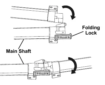
Unfolding the Main Shaft: Push the Folding Lock to the unlocked position to unfold the shaft. Once fully open, push the tip of the Folding Lock into the mating portion and rotate to the locked position.
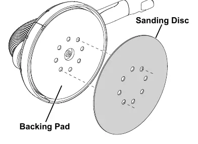
Attaching the Sanding Disc: The sander uses a hook & loop system. Align the eight holes in the sanding disc with the eight dust extraction holes in the backing pad and press them together firmly.
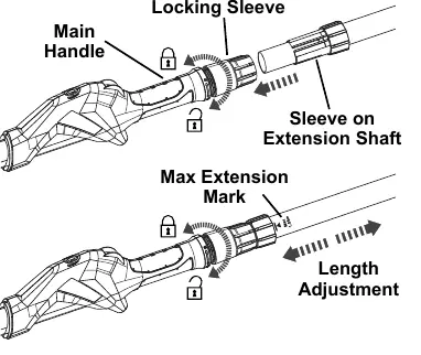
Attaching the Extension Shaft: Loosen the locking sleeve on the main handle. Insert the extension shaft sleeve into the outlet using a twisting motion. Adjust to the desired length (do not exceed the Max 1.65m mark) and tighten the locking sleeve securely.
Dust Extraction Setup: Loosen the locking sleeve on the dust outlet. Insert the vacuum hose connector and tighten the sleeve. Use the hose adaptor if necessary to connect to a dust collection system or vacuum.
Operation
Starting the Tool: Ensure the power switch is in the off-position before plugging in. Press the power switch forward to start. Press down on the front of the switch to lock it ON. Pull the switch backward to turn the sander OFF.
Vacuum Adjustment: Move the Vacuum Adjustment Ring over the opening in the vacuum hose connector to control airflow. Vacuuming power is lowest when the opening is uncovered and highest when completely covered.
Sanding Technique: Grip the tool firmly with both hands. Wait for the tool to reach full speed before contacting the surface. Keep the sanding head flat against the work surface and move in a uniform pattern. To sand closer to edges, pull the brush segment straight out.
Maintenance
Cleaning: Before each use, inspect for loose hardware, damaged cords, or misaligned parts. After use, wipe external surfaces with a clean cloth. Periodically blow dust out of motor vents using dry compressed air.
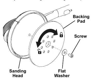
Replacing the Backing Pad: Wear heavy-duty gloves. Hold the backing pad firmly and turn the screw counterclockwise to remove it. Remove the flat washer and the old pad. Install the new pad, replace the washer and screw, and tighten securely.
Troubleshooting
If the tool will not start, check the power connection, circuit breaker, or thermal reset button. If the tool operates slowly, reduce pressure on the workpiece or check the extension cord size. If the tool overheats, allow it to work at its own rate and clear the motor vents.
Practical help
Common problems
Tool will not start
Check that the cord is plugged in, verify power at the outlet, check the circuit breaker, or press the thermal reset button on the tool.
Tool operates slowly
Decrease pressure applied to the workpiece or eliminate the use of an undersized extension cord.
Overheating
Allow the tool to work at its own rate, clear blocked motor housing vents, or ensure the extension cord is the correct gauge.
Tool does not sand effectively
Confirm the sanding disc is pressed firmly onto the backing pad or replace the disc if worn or damaged.
Before use
- Inspect the tool for loose hardware or damaged parts.
- Ensure the power switch is in the off-position before plugging in.
- Wear ANSI-approved eye protection and NIOSH-approved breathing protection.
- Ensure the sanding disc is properly attached to the backing pad.
- Check that the vacuum hose is securely connected if using dust extraction.
Show more Show less
Specs in practice
- Electrical Rating
- 120VAC / 60Hz / 5A power requirements.
- No Load Speed
- The rotational speed range of 600–1500 RPM.
- Max. Accessory Diameter
- The maximum size of sanding disc compatible is 9 inches (225mm).
Images and diagrams
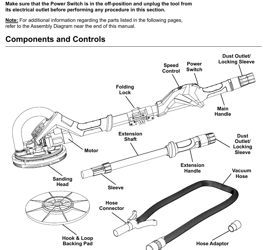
- Components and Controls diagram (Page 9) identifies the main handle, speed control, and dust outlet.
- Vacuum Adjustment Ring settings (Page 12) show how to control suction power.
- Backing Pad replacement diagram (Page 13) illustrates the screw and washer removal process.
Model compatibility
- Use only accessories specifically designed for this sander.
- Do not use accessories that require liquid coolants.
- Use proper sized sanding disc paper to avoid laceration hazards.

Manual page author
Emily Carter
User documentation editor