Industrial / Access Control
Installation and Programming Guide for BEA 10KEYPADU Access Control Keypad
Comprehensive installation and programming guide for the BEA 10KEYPADU and 10KEYPADUSL stand-alone access control keypads. Includes wiring diagrams, setup instructions, user code management, and technical specifications.
Table of contents
Manual images
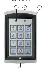
Click an image to enlargeImportant Information
This guide covers the installation and programming of the BEA 10KEYPADU and 10KEYPADUSL stand-alone access control keypads. Before beginning, ensure you have the correct power supply and follow all safety precautions. The device features two zones for user codes and supports various configurations including unlocking times, buzzer settings, and tamper alarms.
Technical Specifications
- Supply voltage: 12 – 24 VAC/VDC. Warning: Do not exceed 30VDC or 24VAC to avoid damage and voiding the warranty.
- Max user codes: 1100 (1000 for zone 1, 100 for zone 2).
- Relay output: 2 Form-C relays (1A resistive).
- IP rating: IP66 (waterproof and dustproof).
- Operating temperature: -22 to 158 °F.
Mounting and Installation
Follow these steps to mount the keypad:
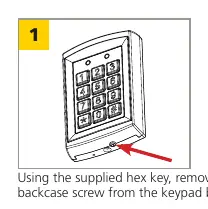
- Use the supplied hex key to remove the backcase screw from the bottom of the keypad.
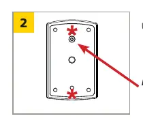
- Use the drilling template to mark and drill the required holes. For surface mounting, use the 4 corner holes. For single-gang box mounting, use the 2 holes marked with an asterisk.
- Mount the backcase to the wall using the provided screws, ensuring the keypad cable is pulled through the center hole. Keep the keypad horizontal to the floor.
- Tip: Add threadlocker to all screws before installing and tighten firmly.
Wiring
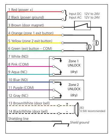
Connect the wires according to the wiring diagram. Ensure all power is shut off before beginning wiring procedures. The system supports connections for power, door magnet, exit buttons, and two zones of unlock relays. A shielding line is provided for ground connection.
Programming
To enter setup mode, enter the default administration code (1234) twice. The Mode LED will turn red. Press the '#' key to exit setup mode at any time.
Admin Codes
- Change length: Enter setup mode, press '*', then '9', then '0', then '4'. Enter the desired length (2-6 digits). Note: Changing length deletes all existing user codes.
- Modify code: Enter setup mode, press '*', then '3'. Enter the new code twice.
User Codes
You can add user codes to Zone 1 or Zone 2:
- Zone 1: Enter setup mode, press '*', '9', '0', '2'. Enter a 3-digit location (000-999), then the new user code.
- Zone 2: Enter setup mode, press '*', '9', '0', '3'. Enter a 2-digit location (00-99), then the new user code.
To remove a user code, enter setup mode, enter the location of the code, and press '*' twice.
Additional Features
- Unlocking Times: Set the duration for Zone 1 or Zone 2 relays (00-99 seconds). '00' sets toggle mode.
- Buzzer/Backlight: Can be turned on or off via specific key combinations in setup mode.
- Door Bell: Connect an external 8Ω, 0.5W speaker to the brown/white and black/white wires. Press '*' to ring.
- Tamper Alarm: If enabled, the buzzer activates if the keypad is removed from the wall.
Factory Restore
To restore factory defaults, enter setup mode, press '*', then '8', then '9' twice. This clears all user codes and resets the admin code and length.
Manufacturer information
BEA Sensors
Practical help
Common problems
Forgot administration code
Turn off power, press and hold the '#' key, and turn the power back on. The code resets to 1234.
Keypad disabled
Occurs after 3 invalid consecutive entries; the keypad will be disabled for 60 seconds.
Tamper alarm active
The alarm triggers if the keypad is removed from the wall. It stops automatically in 60 seconds or if the admin code is entered.
Incorrect key combination
A continuous beep will be heard if an invalid combination is entered.
Before use
- Verify supply voltage is 12-24 VAC/VDC.
- Do not use with BEA 1024VAC transformer or non-regulated 24VAC transformers.
- Shut off all power before starting wiring.
- Apply threadlocker to screws before installation.
- Ensure the keypad is mounted horizontally.
Specs in practice
- Supply voltage
- 12-24 VAC/VDC. Exceeding 30VDC or 24VAC will damage the product and void the warranty.
- Max user codes
- Total capacity is 1100 codes (1000 for Zone 1, 100 for Zone 2).
Images and diagrams
- Wiring diagram details connections for power, door magnet, exit buttons, and relay outputs.
- Mounting diagrams illustrate drilling patterns for surface vs. single-gang box installation.
Model compatibility
- Compatible with 10KEYPADU and 10KEYPADUSL (slimline) models.
- Door bell feature requires an external 8Ω, 0.5W speaker.

Manual page author
Michael Turner
Technical manual editor
Reviews PDF manuals for structure, safety notes, and practical product details so readers can find the right information quickly.