Industrial / Access Control
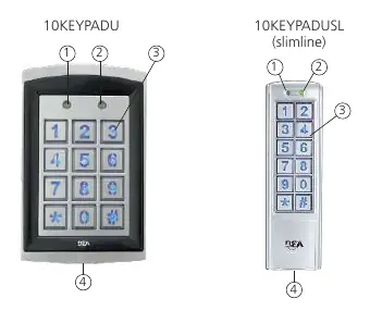
BEA Universal Keypad Family 10KEYPADU and 10KEYPADUSL Access Control Keypad
Quick guide for BEA 10KEYPADU and 10KEYPADUSL access control keypads. Includes wiring diagrams, installation steps, programming instructions for admin/user codes, and technical specifications.
Table of contents
Manual images
Click an image to enlargeQuick Guide
This document provides installation and programming instructions for the BEA Universal Keypad Family (10KEYPADU and 10KEYPADUSL). Key operations include:
- Default Admin Code: 1234.
- Enter Setup Mode: Enter the admin code twice (e.g., 1234 + 1234). The Mode LED will turn red.
- Exit Setup Mode: Press the '#' key. The Mode LED will turn green.
- Reset Admin Code: If forgotten, turn off power, press and hold '#', then turn power back on.
Technical Specifications
- Supply Voltage: 12 – 24 VAC/VDC. Warning: Do not exceed 30VDC or 24VAC. Do not use non-regulated 24VAC transformers.
- Relays: 2 relays (free of potential change-over contact).
- Max User Codes: 1100 (1000 for zone 1, 100 for zone 2).
- IP Rating: IP66 (waterproof and dustproof).
- Operating Temperature: -22 – 158 °F.
Mounting and Installation
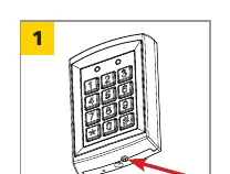
- Remove Backcase: Use the supplied hex key to remove the screw from the bottom of the keypad.
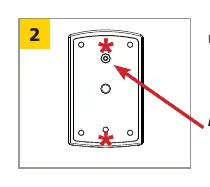
- Drilling: Use the drilling template. Drill 4 corner holes for surface mounting or 2 holes marked with an asterisk for single-gang box mounting.
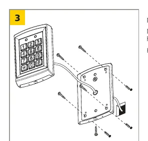
- Mounting: Pull the keypad cable through the center hole and mount the backcase to the wall using provided screws. Keep the keypad horizontal.
Wiring
Connect the 14 wires according to the diagram:
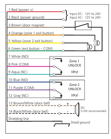
- 1 (Red): Power +
- 2 (Black): Power ground
- 3 (Brown): Door magnet
- 4 (Orange): Zone 1 exit button
- 5 (Yellow): Zone 2 exit button
- 6 (Green): Exit button COM
- 7 (White): Zone 1 NO
- 8 (Pink): Zone 1 COM
- 9 (Aqua): Zone 1 NC
- 10 (Blue): Zone 2 NO
- 11 (Purple): Zone 2 COM
- 12 (Gray): Zone 2 NC
- 13 (Brown/White): Door bell
- 14 (Black/White): Door bell
Programming
Admin Codes
To change the admin code length or modify the code, enter setup mode, then use the '*' key followed by the specific function number (e.g., '*' + '3' to modify code).
User Codes
To add a user code, enter setup mode, press '*' + '9', then '0' + '2' (for zone 1) or '0' + '3' (for zone 2). Enter the electronic location (3 digits for zone 1, 2 digits for zone 2), then the new user code.
Unlocking Times
Set unlocking time by entering setup mode, pressing '*' + '1' (zone 1) or '*' + '5' (zone 2), and entering a 2-digit number (01-99 seconds). '00' sets toggle mode.
Optional Features
- Buzzer: Can be turned on or off via setup mode ('*' + '2').
- Backlight: Can be turned on or off via setup mode ('*' + '2').
- Tamper Alarm: Activated via setup mode ('*' + '6'). If the keypad is removed from the wall, the buzzer sounds for 60 seconds or until the admin code is entered.
Manufacturer information
BEA Sensors
Practical help
Common problems
Forgot administration code
Turn off power, press and hold '#' key, turn power back on. Code resets to 1234.
Keypad disabled
Occurs after 3 invalid consecutive entries; keypad is disabled for 60 seconds.
Incorrect key combination entered
A continuous beep will be heard.
Before use
- Verify supply voltage is 12-24 VAC/VDC.
- Ensure power is off before attempting wiring.
- Check wiring placement to avoid interference with moving door parts.
- Use threadlocker on all screws during installation.
- Ensure compliance with ANSI A156.10 safety standards.
Specs in practice
- Supply voltage
- 12-24 VAC/VDC. Do not exceed 30VDC or 24VAC to avoid damage.
- Relay output
- Free of potential change-over contact; max 1A resistive load.
Images and diagrams
- Wiring diagram details 14 specific wire connections for power, exit buttons, and relay outputs.
- Mounting diagram illustrates the removal of the backcase screw and drilling patterns for surface vs. single-gang box installation.
Model compatibility
- Not compatible with BEA 1024VAC transformer.
- Not compatible with standard non-regulated 24VAC transformers.

Manual page author
David Miller
Documentation analyst
Organizes user manual content into clear summaries, with attention to model details, product context, and everyday usability.